
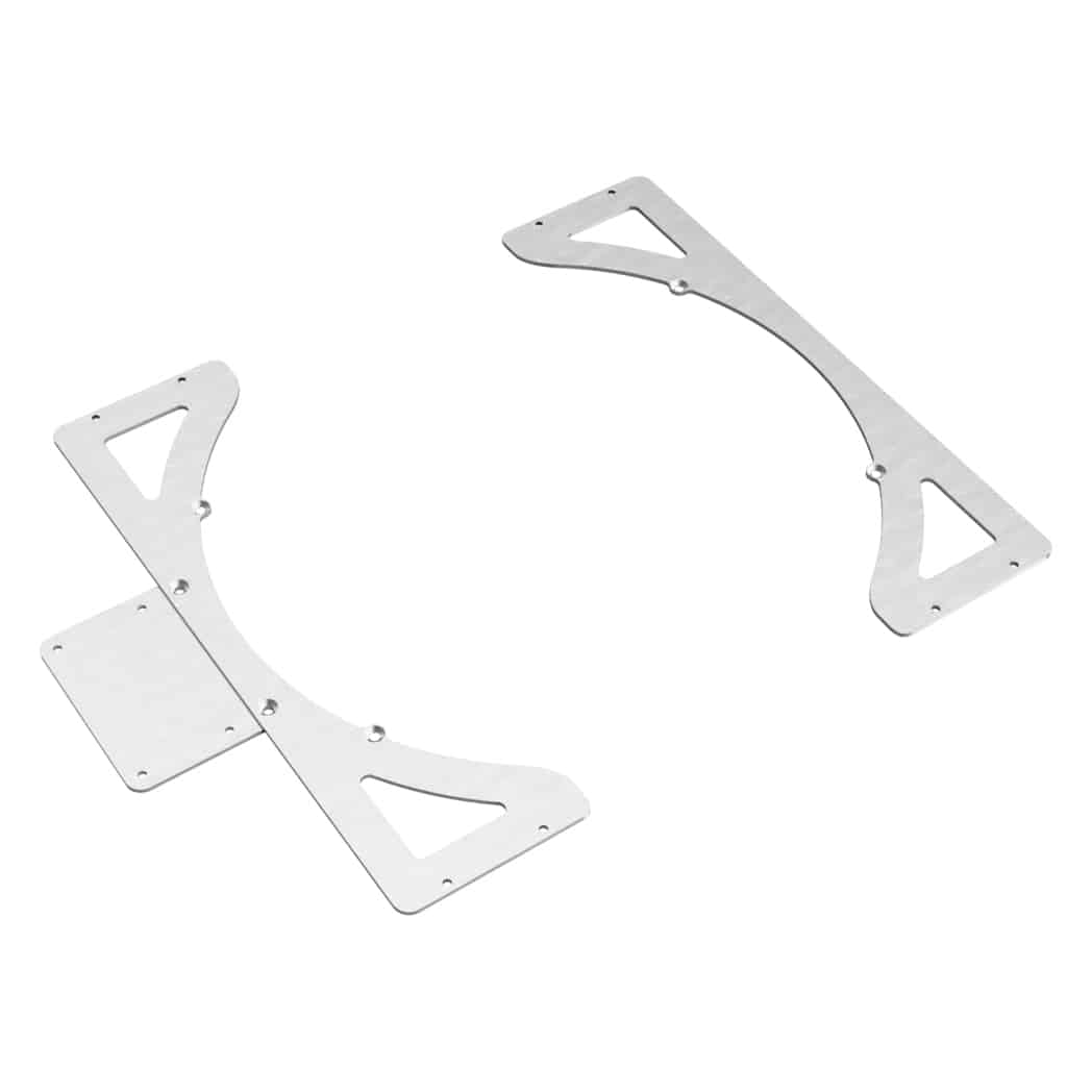
N15 Design E46 M3 Electric Fan Mount DIY
The stock fan clutch cooling setup does a great job on our S54 engines, however sometimes it’s not enough. To add another layer to the situation, if your fan blades grenades inside your engine bay you can cause destruction to your hose, radiator, hood and other surrounding parts.
The N15 Design E46 M3 Electric Fan Mount is a great way to add a 16″ SPAL electric fan because it’s so easy to install. In addition, the AUX Fan Controller Mount (optional) allows you to retain the stock controller to run the fan on auto as an OEM style would. Don’t get intimidated of the crazy electric fan setups and the false “requirements” to run a fan controller. This one is truly easy to install.
Tools Required
- N15 Design E46 M3 Electric Fan Mount
- 16" SPAL fan or similar (SPAL 2024 16" Puller Fan 30102049 - $151.56)
- 4mm hex bit
- T25 torx bit
- 10mm socket
- 19mm socket
- 8mm wrench
- 32mm wrench
- Ratchet
- 3/16" drill bit
- Drill
- Wire stripper [amazon_link asins='B000OQ21CA' template='PriceLink' store='builjour-20' marketplace='US' link_id='ece54d1d-aff0-4bb8-8b56-740a4e811397']
- BMW Water Pump Pulley Locking Tool $25.95
- Coolant
- Funnel
Install Directions
1. Remove intake duct using needle nose pliers to remove all 4 clips.

2. Remove radiator fan shroud and fan.
2.2 Remove the 3 push pins holding the shield. There is one on top directly center, one driver and one passenger. Remove using pliers. I don’t have pictures of the passenger side of the shield because I don’t run that. This is a picture of the driver side shield.

2.3 There are a total of four T25 torx screws (one on each corner) and 2 plugs on the passenger side of the radiator/shroud. Unplug cables first, then remove the four screws. The passenger side top torx screw (pictured below) is longer than the others. Tape up plugs and set aside.

2.4 Remove passenger side lower screw.

2.5 Remove fan using the E46 M3 BMW Water Pump Pulley Locking Tool and a 32mm wrench. The fan clutch nut is reverse threaded. Lock in the water pump pulley and unscrew using the 32mm wrench. Spin the fan to unscrew a little faster, but make sure you don’t let the fan drop.

3. Remove radiator and drain coolant from lower radiator hose.
3.1 Remove the upper radiator hose as well.

4. Remove front pusher fan. I don’t have a detailed step with pictures for this part, but you’re going to need to remove your front bumper as well as your kevlar/aluminum bumper beam in order to access the front pusher.

5. Install OEM AUX Fan Controller.
5.1 Once the fan is out, you can locate the AUX Fan Controller.
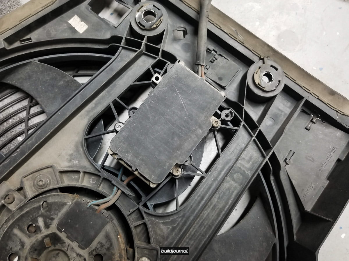
5.2 Cut the brown and blue wires on the fan motor side.

5.3 Install the AUX Fan Controller on the bracket.

5.4 Cut the black and red wires on the 16″ SPAL fan right before the plug. Don’t cut it too short as you’ll need all of the wires.

5.5 Solder or crimp the wires.
Black to Brown
Blue to Red

5.6 Apply heat shrink.

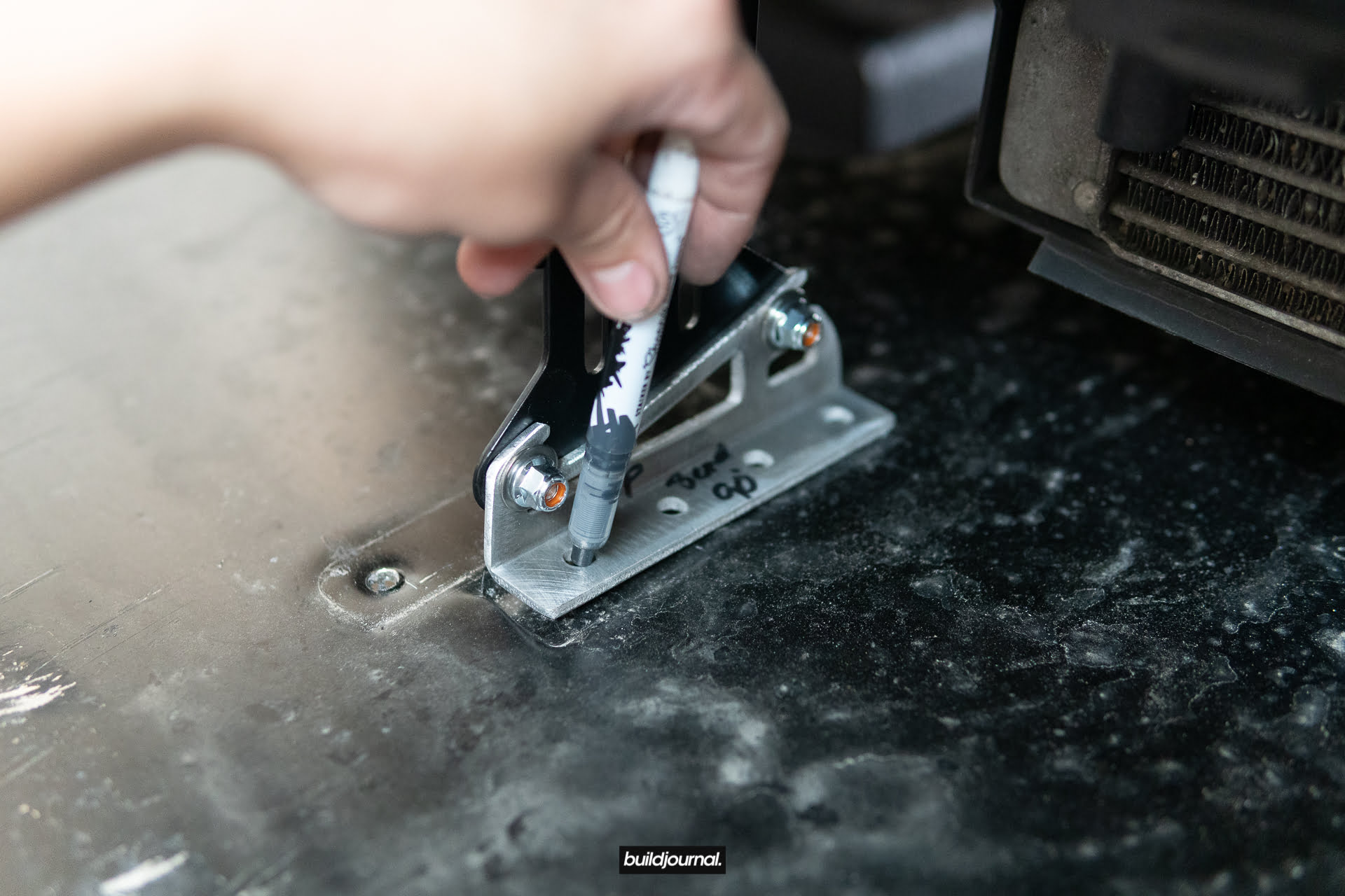
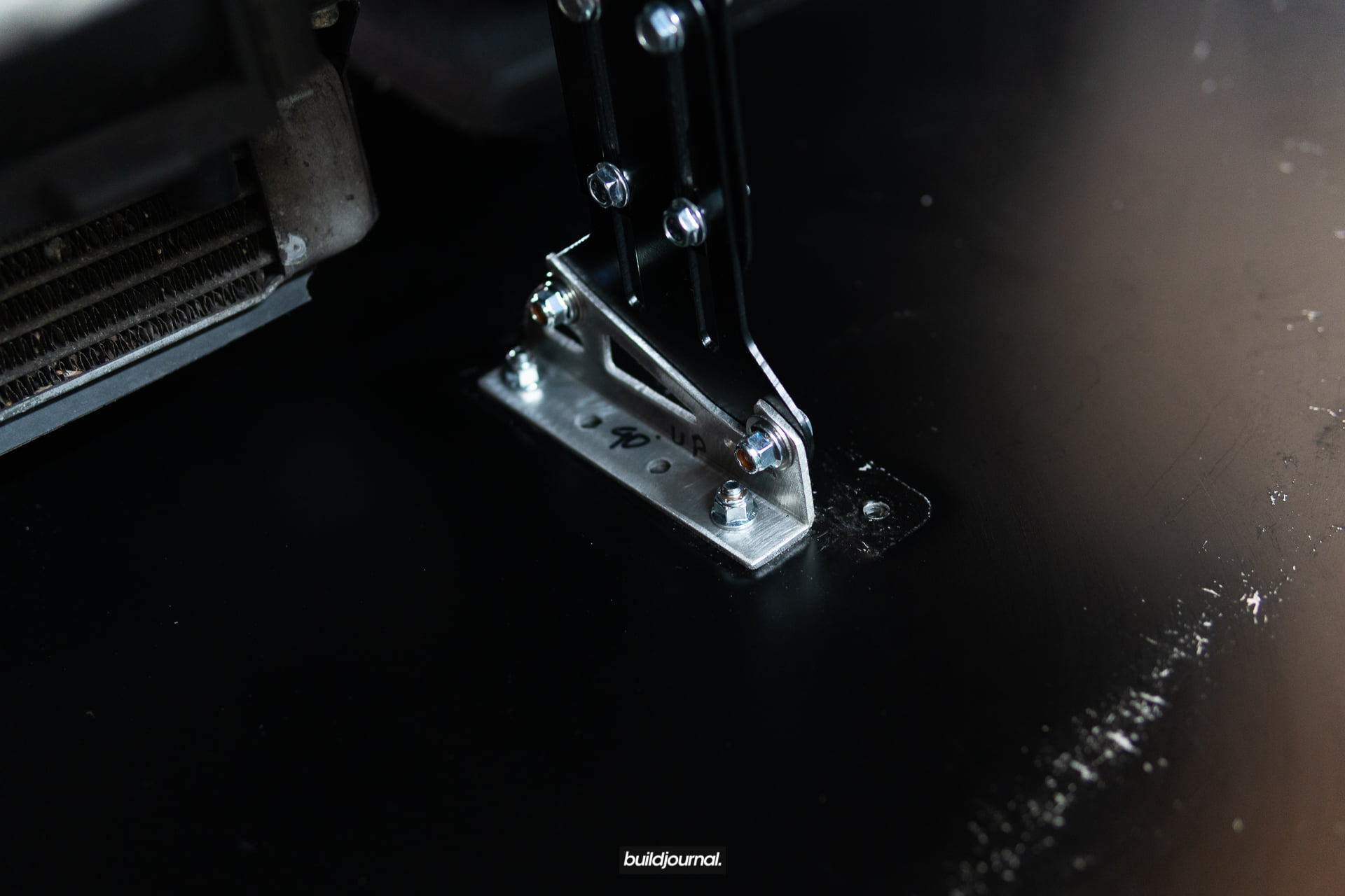
6. Mount fan/bracket to radiator for drilling holes.
6.1 Align the fan to the passenger side of the radiator. It’s up to you on where to mount it, but I recommend the driver side because of the fan might hit the water pump.
6.2 Mark holes and drill. I used a 3/16″ drill bit.
6.3 Test fit the hardware and remove the bracket/fan once you’re done creating the mounting points.

7. Install radiator back in.

8. Install fan using supplied hardware.
8.1 Plug in the fan using the stock connector.
8.2 Tuck wiring away from the belts and water pump. I zip tied mine to the back of the fan case.
8.3 Add coolant inside the system if you chose to drain your radiator in Step 3.
8.4 Bleed the cooling system properly. During this procedure the fan should turn on.


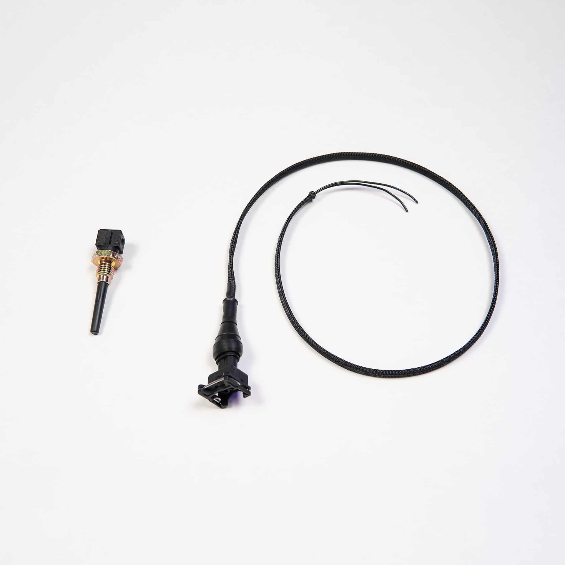
E46 M3 IAT Sensor Relocation DIY
The intake air temperature (IAT) sensor is integrated into the E46 M3 stock MAF location inside the intake tube and although the OEM location works, it is prone to heat soak which will allow the ECU to pull timing resulting in power loss. We made this IAT relocation kit so we can move the sensor location to a location outside the MAF that is optimized for air flow thus the engine is less likely to pull timing due to false temperature readings.
The install is fairly simple, but you will need to solder two wires together. There are some vendors that sell a plug and play harness so if you don’t want to cut and solder your stock MAF wires you can purchase their kit.
Tools Required
- Soldering kit (including soldering wire) [amazon_link asins='B06XZ31W3M' template='PriceLink' store='builjour-20' marketplace='US' link_id='74082f78-8dd9-40e1-9903-ca49edc52f5d']
- Shrink tube [amazon_link asins='B075WR9FVL' template='PriceLink' store='builjour-20' marketplace='US' link_id='3f69cf49-a1b5-4d36-b69c-d4ab4bcfee01']
- Wire cutter [amazon_link asins='B000OQ21CA' template='PriceLink' store='builjour-20' marketplace='US' link_id='309825f7-3e61-4369-854d-60fba522382a']
- Razor blade [amazon_link asins='B0006O5JR4' template='PriceLink' store='builjour-20' marketplace='US' link_id='14117261-e1ce-451e-bb96-50ddc8c5c444']
- Lighter
- Electric tape
- Scissors
- IAT relocation sensor kit
Install Directions
1. Remove MAF and locate the wires numbered 1-5. Remove rubber grommet.
2. Cut and remove some of the plastic wiring loom with scissors then cut Wire #1 about 2″ down from the plug.

3. Wire #1: using the wire stripper, expose about 1/2″ of bare wire on the ECU side of the wire. (opposed to the plug side)

4. Wire #3: using a razor blade, skin and expose about 1/2″ of bare wire; do not cut.
5. Wire #3: use a razor blade to split the wires in half creating a gap to insert IAT wire.

6. Get one of the IAT sensor wire (doesn’t matter which wire) and insert a heat shrink tube. We will heat shrink once it’s soldered.

6. Split the ends of the Wire #1 and the IAT wire to mate for soldering.
7. Twist the wires.

8. Get the other IAT wire and insert into the hole you created in Wire #3 in step 5. You don’t need to split the wires on the IAT wire.

8. Twist the wires.

9. Your wires are ready for soldering. Solder both wires.
How to Solder: Watch Video

11. Use a lighter to heat shrink the tube for Wire #1.
12. Use electric tape to wrap Wire #3.

13. Tape and heat shrink the exposed (plug side) Wire #1.

14. Insert rubber grommet and install on MAF sensor.
Okay so now that we have the IAT sensor wired up, we need to install the IAT sensor somewhere. I’m leaving this step open ended because the IAT installation depends on which intake you’re running.
Personally for me I’m running the Eventuri intake so I decided to drill a hole in the intake bracket right below the filter. This works perfect because my PSDesigns Headlight Duct kit allows air right into the filter and IAT sensor.


I assume most of you are running the stock box. The IAT sensor can be installed on the lower half of the intake box right above the drain outlet. All you need is a 7/16″ drill bit to create a hole in the box. M3support.net user “s54smg2” did an excellent write up for the IAT relocation on S54 intake.
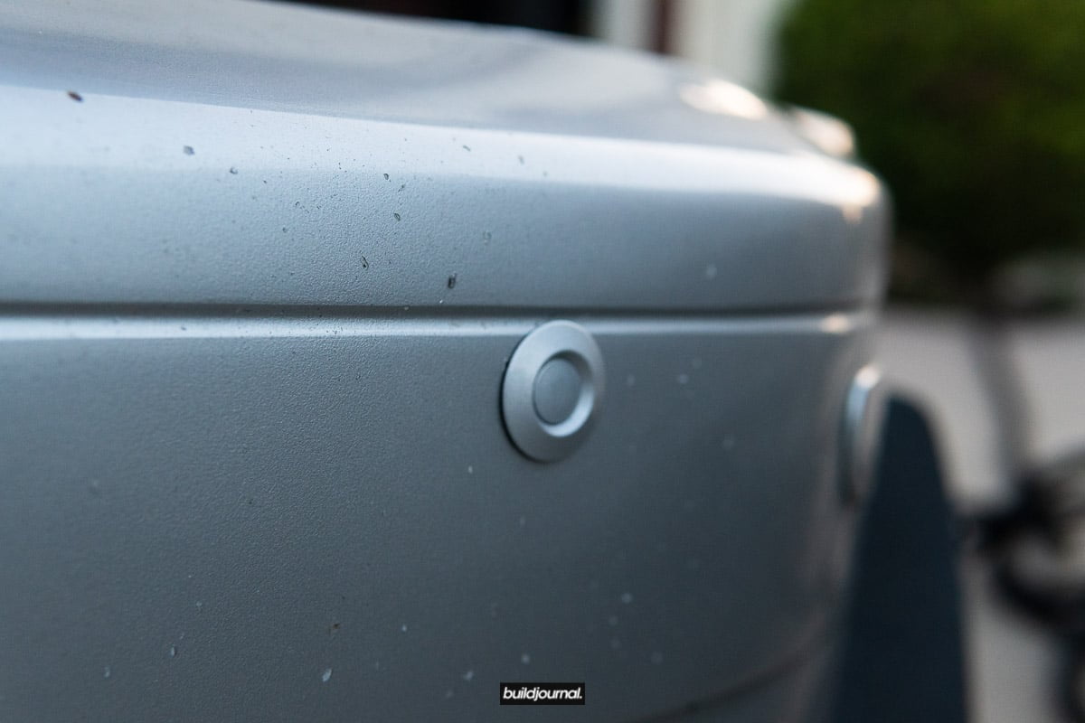
Remove Your Bumper in Seconds, Pop Latch Quick Release for Front Bumper DIY
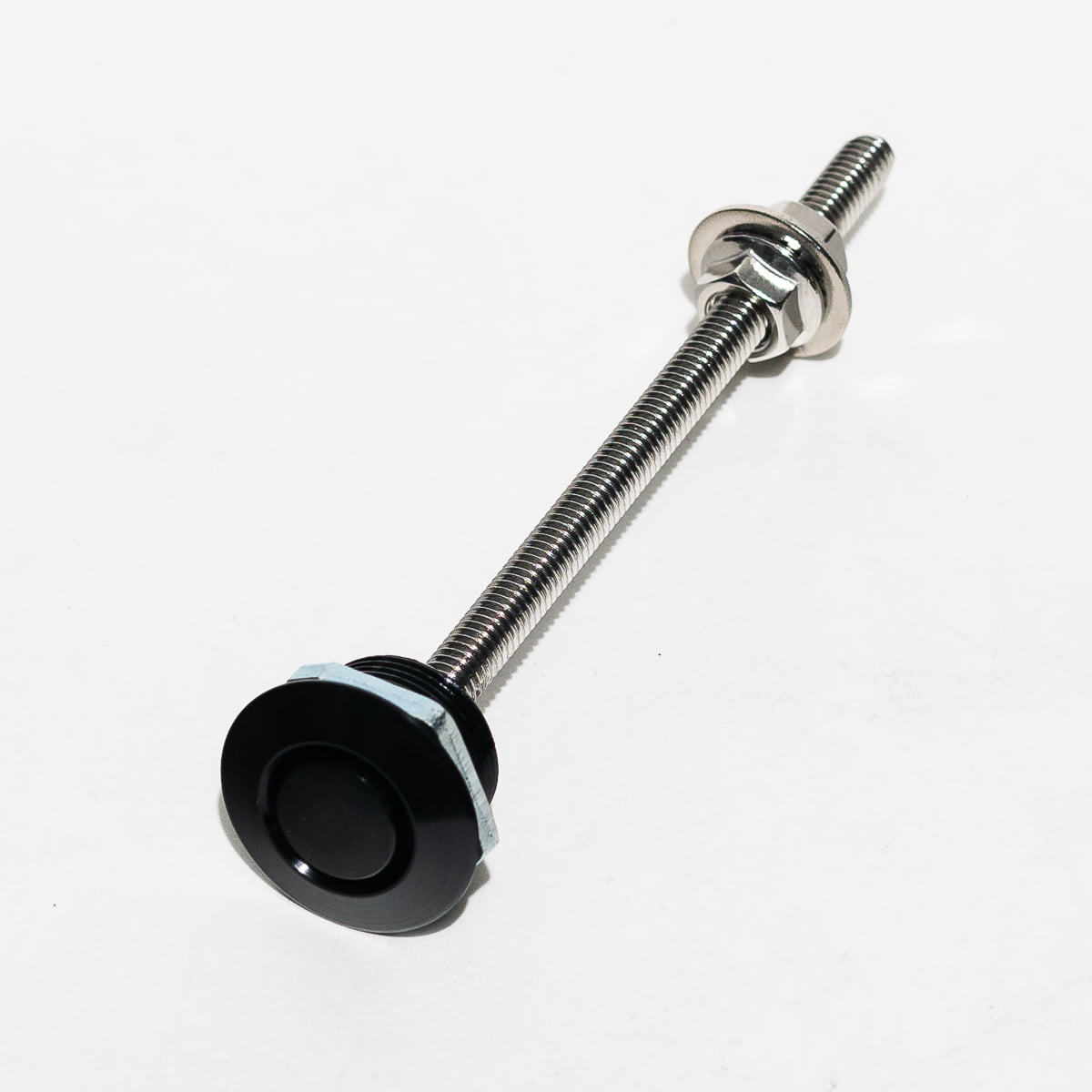
Instantly remove your front bumper cover in seconds! We’ve released a custom mounting solution for the Pop Latch Quick Release and we’re going to show you how to do the install. The studs use the factory hex stud location on Kevlar bumper supports for an easy bolt-on installation. Oh also, we now offer custom paint matched latches as an add-on option!


Install Directions
1. Remove front bumper
2. Locate the outer hex stud on the Kevlar bumper

3. Remove stud using a hex drive
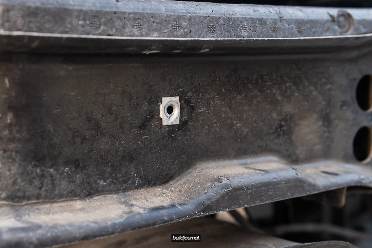
4. Remove thread insert and install new stud from Pop Latch kit
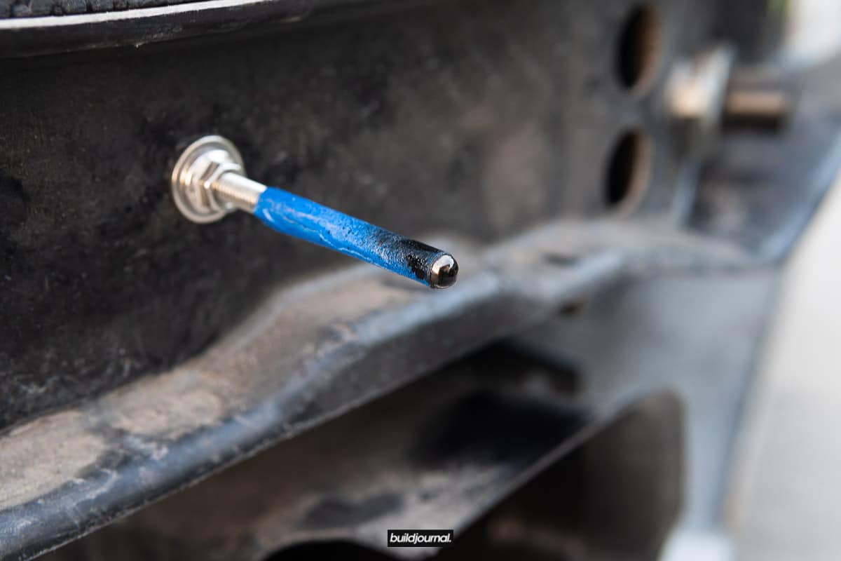
The Kevlar bumper has a hollow inside and you can get to the opening through the immediate sides of the support beam. Once the stud is inserted, you must back the stud towards the back and lock it down with the supplied washer/nut. The back of the stud should be almost touching the backside of the hollow bumper beam.

For Aluminum bumper carriers, you will be required to drill a hole through the carrier.
It is up to you to select which area to create the hole for the stud.

This is the back side of the Aluminum carrier.

5. Tape up the stud and expose the tip, then apply paint or wet marker
Here we are going to line up the bumper and mark the inside of the bumper to create a spot for the pilot drill bit.
6. Place a strip of tape on the side of the bumper so the paint/marker can leave a mark, push bumper in and create mark
When you push in the bumper, do not push too hard or you may cause paint cracks on the bumper.

7. Drill pilot hole

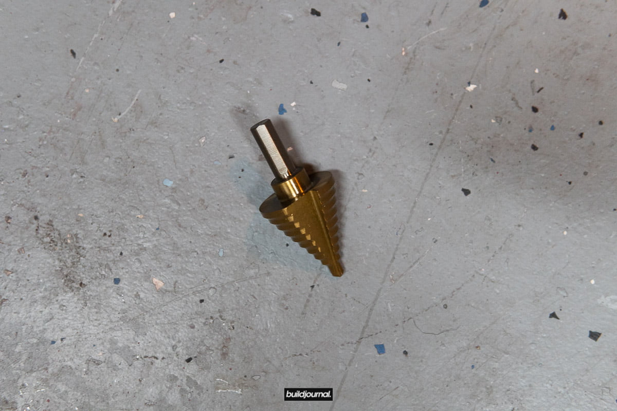
8. Using a 13/16 bit or step drill create a cutout on the bumper
9. Insert the Pop Latch Quick Release into bumper and secure with locking nut

10. Break off the outer portion of the bumper foam support (optional)
If you choose to keep the full foam piece, you will have to drill out the foam to make room for the latch. The bumper is fully supported without the side pieces.
11. Repeat the same steps for the other side

Aerodynamics
-
-
Trackspec Hood Vent Kit - E46 M3
Price range: $359.99 through $367.99-

-

-
Trackspec Hood Vent Kit - E85 Z4 M
Price range: $359.99 through $367.99-

Trackspec Hood Vent Kit (Center) - E90 E92 M3
Price range: $229.99 through $235.99-

-

Trackspec Hood Vent Kit (Sides) - E85 Z4 M
Price range: $359.99 through $367.99-
-
Adjustable Splitter Cable Rods
Price range: $70.00 through $95.00-

Jack Pads - E36
$13.20-

Trackspec Hood Vent Kit (Center) - E36 M3
Price range: $229.99 through $237.99
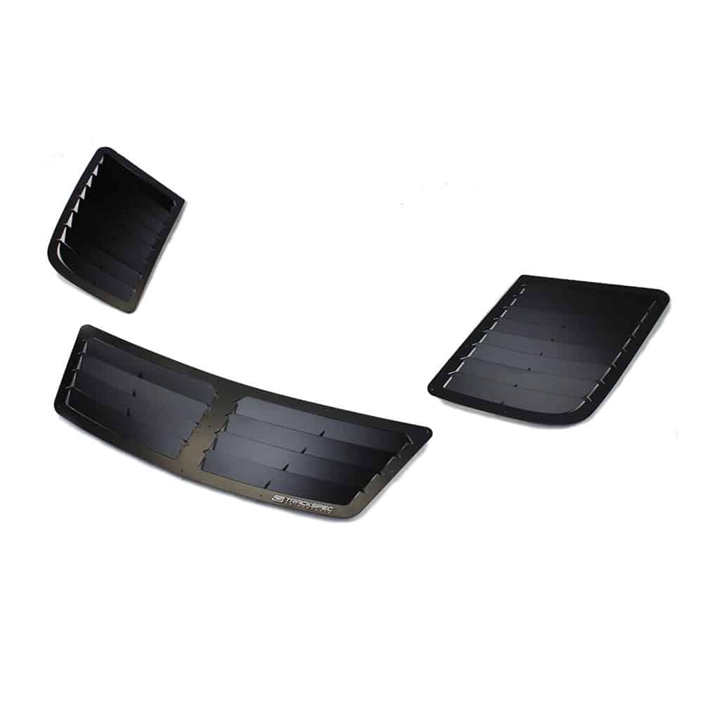
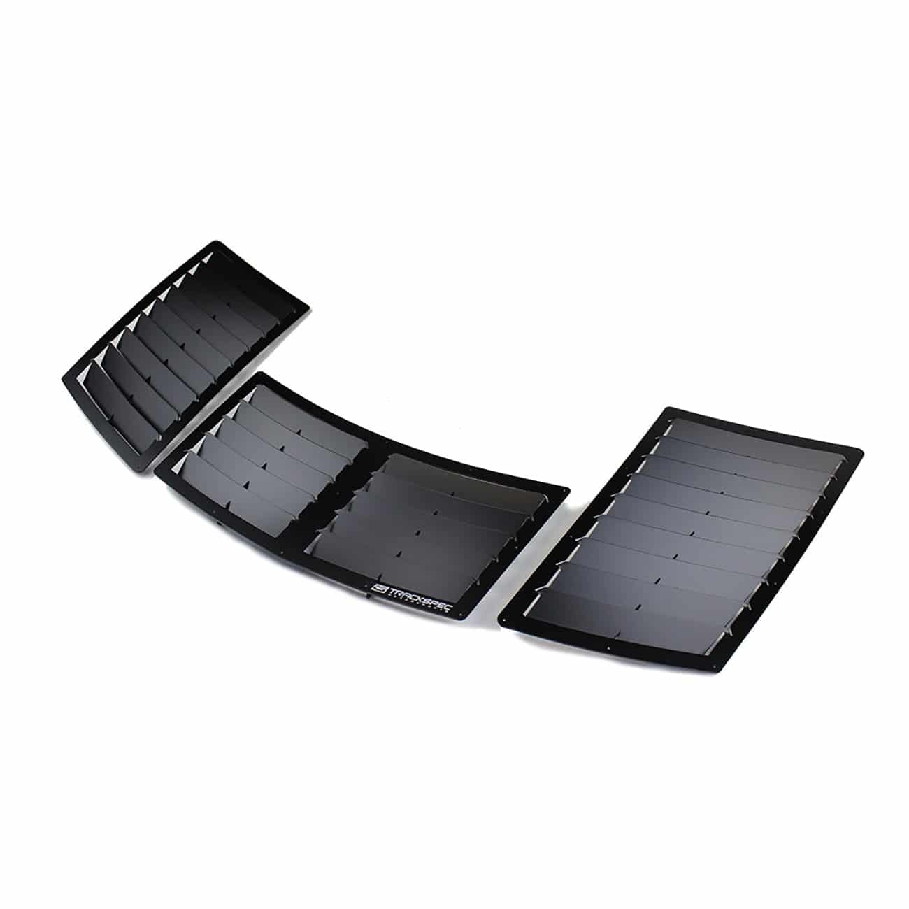
Trackspec E46 M3 Hood Vent Kit Install DIY
Yes you’re going to cut your hood, but don’t be intimidated – it’s not too hard. A properly designed hood vent kit like the Trackspec E46 M3 Hood Vent Kit allows for two major things: heat dissipation for engine cooling and pressure release for improved aerodynamics. A third possibly? It looks bad ass!
There are three different “kits” for the Trackspec hood vents. One is the entire kit and the other two are just sectional pieces. We are now a re-seller for Trackspec so you can purchase the E46 M3 kits here. They sell the 3-piece kit as well as the center only and side only kits.
-
Trackspec Hood Vent Kit - E46 M3
Price range: $359.99 through $367.99-

Trackspec Hood Vent Kit (Center) - E46 M3
Price range: $219.99 through $227.99-

Trackspec Hood Vent Kit (Sides) - E46 M3
Price range: $229.99 through $237.99Required Tools
- Angle grinder
- Dremel Rotary + Reinforced Cut Off Wheel [amazon_link asins='B0006O8RZA' template='PriceLink' store='builjour-20' marketplace='US' link_id='e6ecf1b1-f512-4b4d-a4cd-94ea52c65ea3']
- 100-grit sandpaper or similar or file
- Anti-rust coating paint
- Rivet tool [amazon_link asins='B000NPT74C' template='PriceLink' store='builjour-20' marketplace='US' link_id='58b422a1-e313-4c9e-b119-41b7de13bb8c']
- Work stand [amazon_link asins='B000LQN5GO' template='PriceLink' store='builjour-20' marketplace='US' link_id='67fabdb1-f932-46e9-9816-48a1c9401393']
- String or yarn to measure
- Torx bits
- Ratchet
- Painter's tape
- Safety goggles

Install Directions
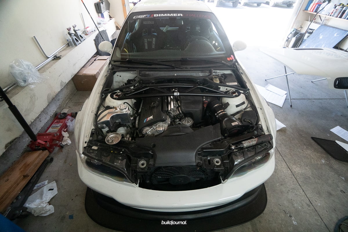
1. Remove hood
Pop open your hood and remove the washer grommet to pull the washer lines and all necessary lines. There will be 2 torx screws on both hinges. You can completely remove the bottom two on each side, but just loosen the top ones since you can slide out the hood. Before you loosen the torx bolts, make sure you mark the bolts so you can re-align it later. Have a second set of hands to catch and remove the hood once loosened.
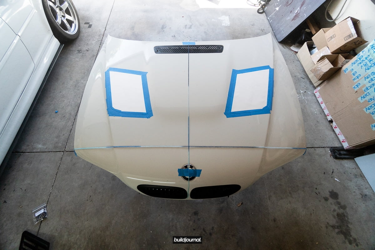
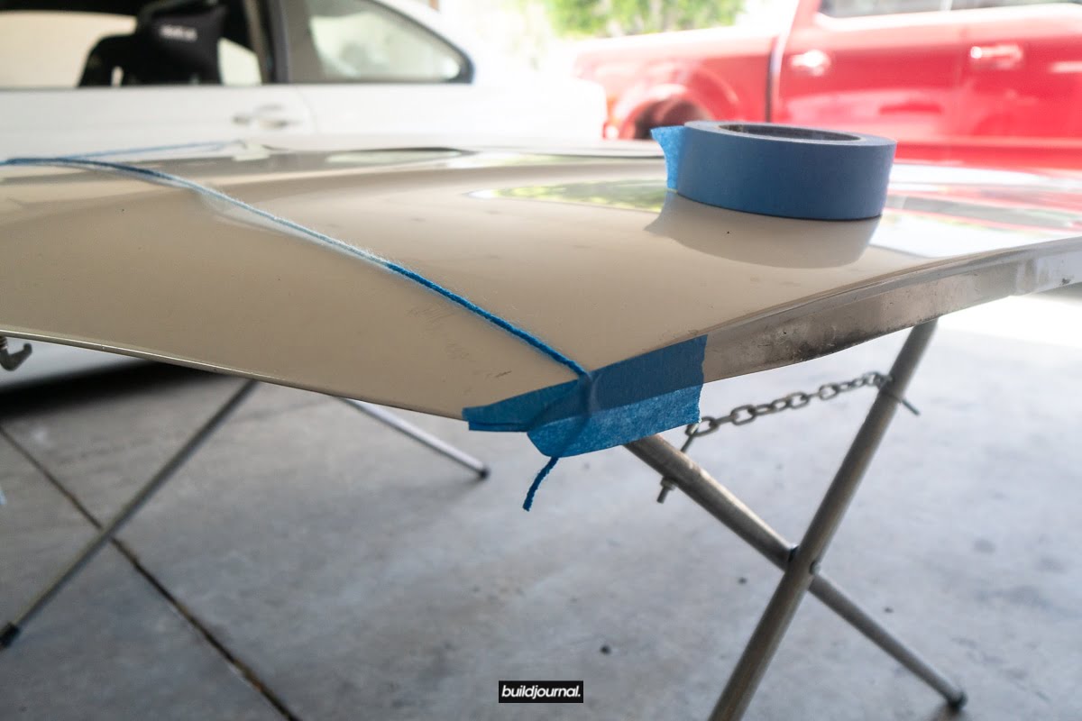
2. Lay gridlines on the hood
Place the hood on a table, workbench or whatever to properly hold the hood. Remember you will be cutting later so you want something sturdy. We’re now going to get some string to place gridlines on the hood so we can align the vent templates properly.
I placed a line going straight down the middle of the hood from the top/middle of the hood and straight down through the BMW emblem.

There’s actually a middle dot in the OEM hood vent that you can use to set your vertical line.
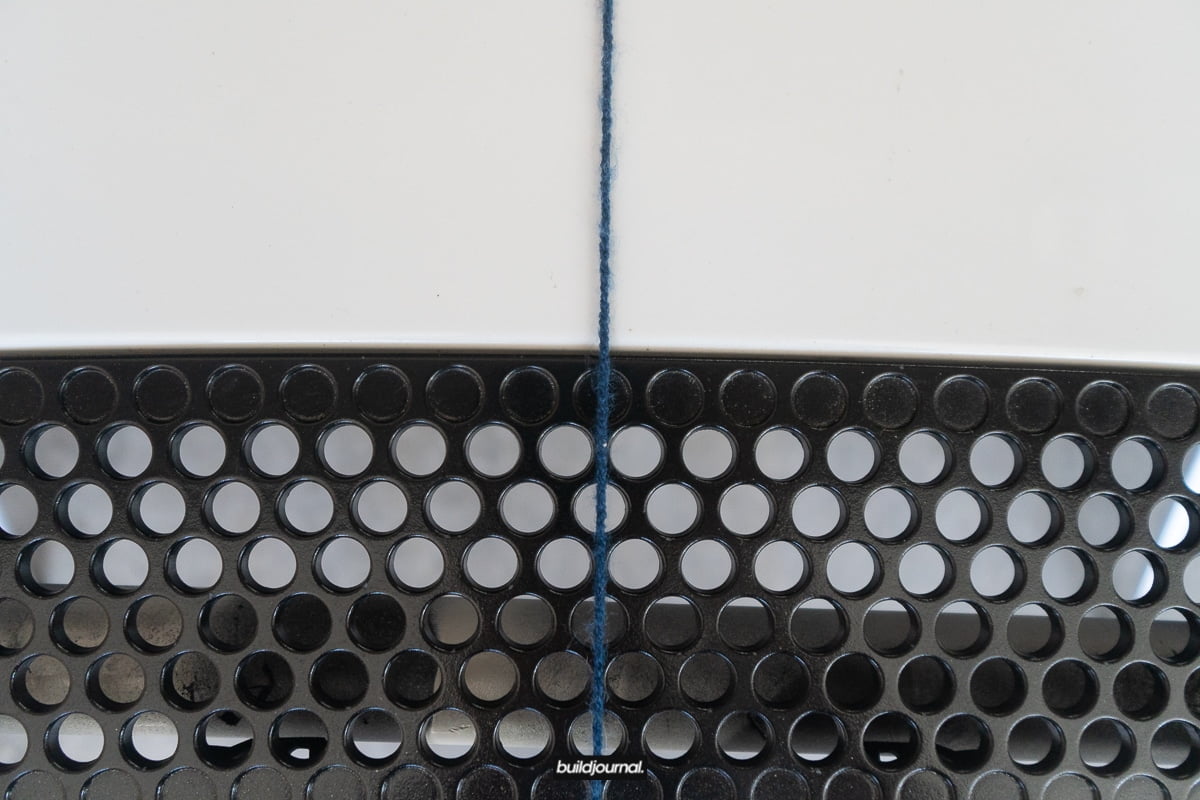
I also placed a second line going horizontally from one corner of the hood to the other. Now that the guidelines are in place, you can either place the louvers exactly how Trackspec has it in their instructions or just place it using your preference. I chose the latter.
3. Tape louver templates
I placed my lovers a little differently, but we’re only talking about an inch or two in difference. As long as you place the louvers in parallel with the natural lines on the hood you’ll be fine. Once you have the templates set, tape it up!

4. Cut hood
There are cut markers on the templates so cutting is easy. Make nice straight cuts first then you can use a dremel to transition the cuts to the corners.

Use a smaller rotary tool like a Dremel to make the cuts on the corners. Make sure to use reinforced cutting wheels for this project since you’re cutting aluminum. And make sure to wear safety goggles!

Both driver and passenger sides of the hood have reinforced structure underneath the hood which you will need to cut through. You’re going to have to cut through a good amount of aluminum framing, but I can confirm it doesn’t sacrifice the structural integrity of the hood even with all that cutting.


5. Test fit and trim
So now once you made the cuts from the template guide, place the appropriate louver inside the cut to test fit. I found that the template is very generous with the cuts so I had to trim for a more clean look.

6. Drill holes for rivets
With the louver lined up for install, drill through one corner first and place a temporary rivet to hold in place while you drill the others.

7. Sand/deburr edges
Get some low grit sandpaper or file to deburr the underside edges of the hood.

8. Install rivets
Now all you need to do is install the rivets.


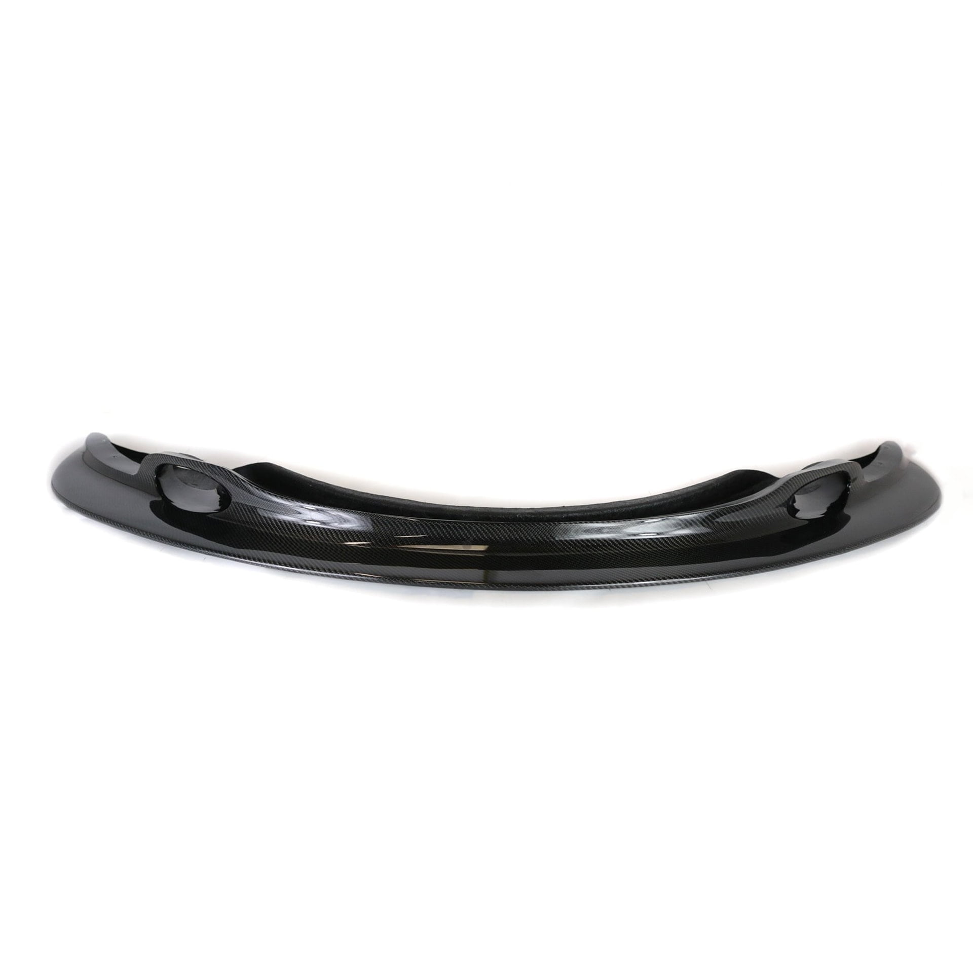
First Time Out With The RS Future Wing at Buttonwillow CW13
First of all a huge thank you to Amir (@that911) for making me this RS Future wing just in time for my track day slash shakedown day before Bimmer Challenge Round 5 at Auto Club Speedway. I always like to say, I’m all about function, but if it doesn’t look good, I don’t fuck with it. I’m glad this wing puts a checkbox in both criterias.
I started the 1st session with some hardware failure so I was forced to retire after the outlap. On the second session, I immediately noticed the car’s imbalanced handling characteristics so I immediately called Amir for some track side support and he was prompt to pick up and discuss some suspension tuning options even though he was out instructing at the track himself. My current spring rates are not ideal for aero and I have a really stiff rear spring to begin with. The wing didn’t help.
On the high speed turns my car would not turn in. It almost felt like I had a broken steering rack. Turns out the front was way too soft so I bumped up the front rebound and softened the rears a bit. The next session I went back out and immediately it felt better, but still lazy. It wasn’t until the fifth and last session, also probably the hottest part of the day, when I felt pretty comfortable with the setup and I started going for time. With my Nexen SUR4 (non-G) tires I managed to clock a 1:58.16 which was a new personal best, however not by much. I’m pretty sure if I ran in the morning sessions I would’ve been a second or two faster.
I plan to make a few more changes to the setup. I’m even thinking about downgrading to the MCS 1WNR setup with stickier tires. Car definitely has potential to be in the 55’s.

E46 M3 Fuel Injector DIY
The stock E46 M3 S54 Bosch fuel injector static flow rate is rated at 260 cubic centimeters (cc) per minute at 43 PSI. The purpose of taking out my injectors were to clean it since a buddy of mine had a flow rate of 150 cc on his injectors after 150K+ miles of usage. Little did I know my injectors were going to be worse! If your car is in the 100K range, I would consider cleaning the injectors. Scroll down through the article to see what that process was like for me, but first we’ll need to take out the injectors. So here is a little DIY for removing and installing injectors.
Difficulty
4/10
Time
4 hr
Cost
$150
Vehicle symptoms for dirty or clogged injectors
If you’re dealing with any of the following symptoms, as stated from injectorrx.com, you most likely have dirty, clogged or leaky injectors.
- Starting issues
- Poor idle
- Failed emissions
- Poor Performance
- Engine does not reach full RPM
- Increased fuel consumption
- Rough engine performance
- Surging and bucking under various throttle loads
- Smoke from the tail pipe
- Engine Knock or Detonation which can lead to catastrophic engine failure
- Pollution
The solution
Get your injectors cleaned! There are several injector cleaning companies you can find. I chose to go to RC Fuel Injection in Torrance, CA since they’re relatively local to my area. They clean, balance and calibrate your injectors to new-like state including new o-rings. They completed my cleaning in less than 24 hours and I was able to pickup the very next day after I dropped off. They also include a test sheet to show the old and new flow rate. Scroll below to see the print out for my injectors. You’d be surprised.
Instructions to remove your injectors for cleaning
1. Remove cabin filter and strut bar
1.1 Remove 4 nuts holding front strut bar.
1.2 Remove 4 torx screws holding cabin filter housing, remove filter.
1.3 Remove strut bar.

2. Drain fuel from lines
2.1 Unplug Fuse #54 from glove box. It should be a yellow 20A fuse.
2.2 Start car up and let engine stall. This will remove most of the fuel in your lines.
2.3 Reinstall the fuel pump fuse back in. Don’t start the car again or else you need to re-do this process over again.
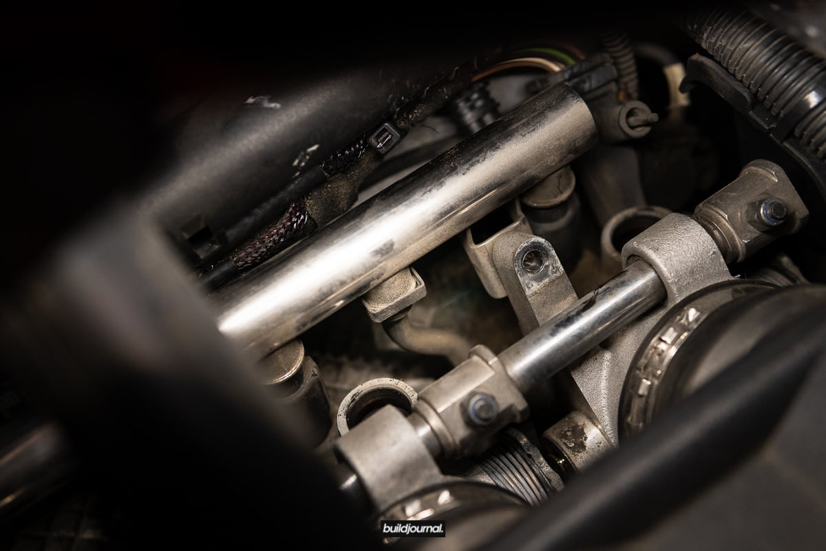
3. Remove Air & Fuel Rail
3.1 Disconnect plenum-side breather valve via squeeze clip.
3.2 Disconnect breather valve on air rail.


3.3 Remove the 2 silver 10mm hex bolts on the air rail. First one is by the TPS sensor above cylinder 1. The second bolt is in the rear between cylinder 5 and 6. I had to use a swivel head to get to it.

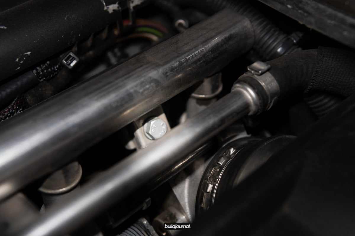

3.4 Disconnect the vacuum tube at the very ar end of the air rail. Be very careful not to drop it down the engine bay as I did!

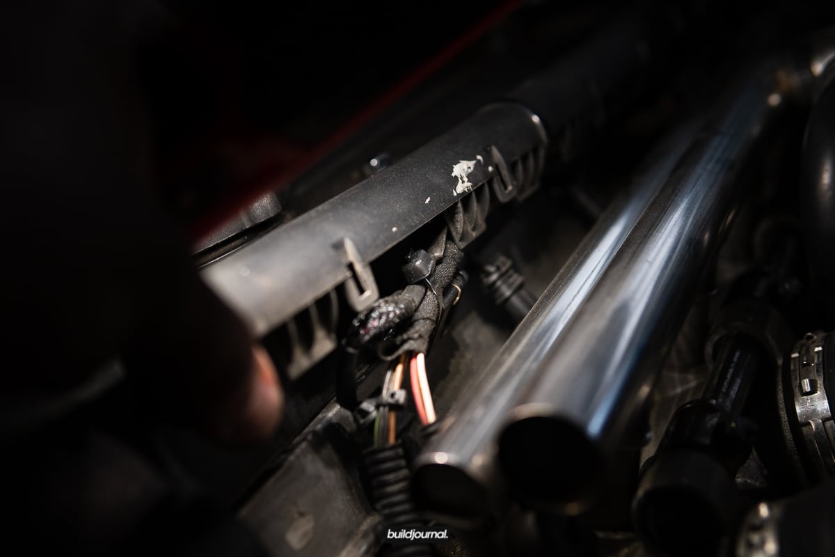
3.5 This step is going to be different for most of you. I have an E85 kit, so my plastic fuel injector harness cover piece was already detached. For those that are stock, you’ll need to unclip the plastic tabs remove. Don’t completely remove the cover, but just unclip it so the air and fuel rail can come out.
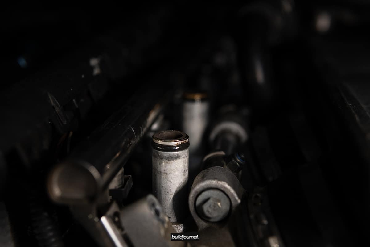
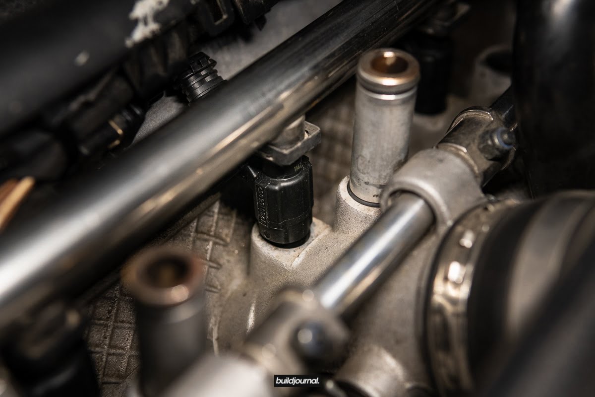
3.6 Use a pry bar against the the engine head to lift the air rail up. Start at the side closest to the front of the car. The air rail is connected via 6 plastic air valves that are pressure fitted via o-rings. Once you pry the first few ones apart, you can lift the remaining.
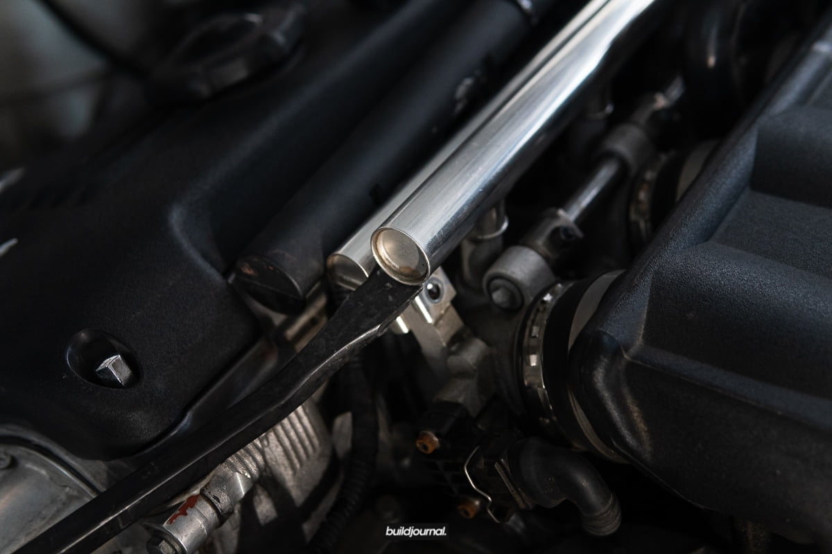
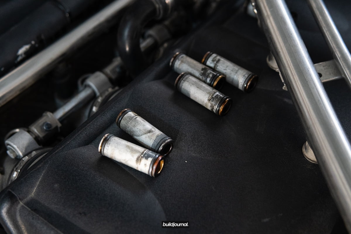
3.7 Remove all 6 air valves by twisting them out. Some will be stuck on the air rail and some on the throttle body. You should clean these before they go back on.
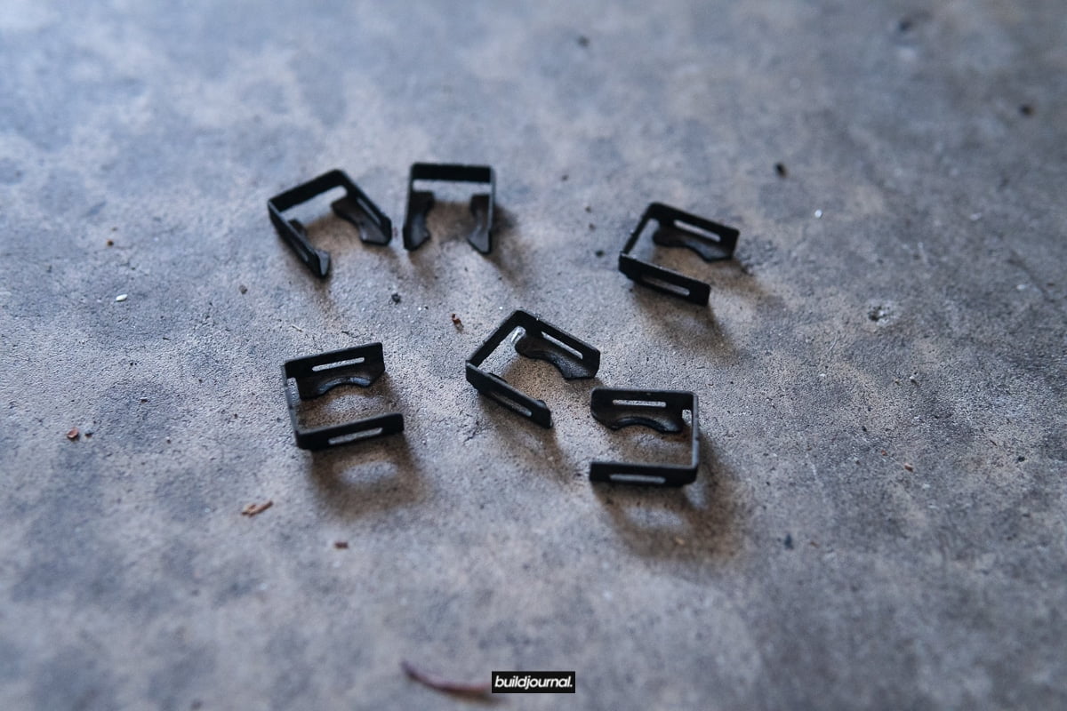
3.8 Now to the fuel rail. There are a total of 6 metal tabs holding in the injectors to the rail and one metal tab holding in the fuel feed line which is located between cylinder 5 and 6 in the rear. Use a flat head to pry the clips apart.

3.9 Pry the fuel rail as you did for the air rail. Injectors will pop out one by one.

3.10 Careful not to pull out the rail all the way just yet. You must disconnect each injector wiring harness.

4. Remove injectors
4.1 Eventually they will all pop out like this attached to the rail. To remove the injectors from the rail, just simply twist them off. They are pressure fitted via o-rings. Take note of the orientation of the injector plugs for re-installation.
5. Cleaning the injectors at RC Fuel Injection
As I mentioned earlier in this article, the stock injectors have a flow rate of 260 cc at 43 PSI. My average flow rate was 185.2 cc with the lowest being at 125 cc. What!


6. Installing injectors
Installing is the trickiest part of this DIY because since the injectors and air valves are pressure fitted with o-rings, it’s really hard to get those back in by pushing down.
6.1 Twist injectors into fuel rail and insert the metal clips you removed in step 3.8. Make sure the clips are seated properly as pictured below.

6.2 Apply some engine oil or silicone grease, in very small amounts, to the o-rings on the air valves to lubricate when installing the air rail back on. Twist in air valves onto throttle body.
6.3 Apply some engine oil or silicon grease to the injector o-rings as well. Dry pressure installation may damage your o-rings. Take the entire fuel rail assembly and install the injectors back in. Watch the injector nozzle alignment as you install. You’re going to need to wiggle each injector to make them slot right in. The 2 threaded metal tabs on the fuel rail will go behind the throttle body mount. Also keep an eye on the fuel feed line alignment between cylinders 5 and 6.
6.4 Once the injectors are in the hole, you’re going to need a good amount of top pressure to fit them in. In my case even with some lubricant, it was very difficult to get them in. I do not advise this method, but I had to get a small mallet to tap the fuel rail to push each injector in. One thing you should make sure to do is make the fuel rail go down evenly. Don’t push in one side completely and expect the other end to line up. Once properly seated, the fuel rail metal tab holes will line up with the throttle body.
6.5 Insert the metal clip for the fuel feed line.
6.6 Install the air rail back in. Same method as fuel rail.
6.7 Install the two 10mm bolts.
6.8 Install the rear vacuum hose back in. Turn the key to the 2nd position (which primes fuel into the lines) and check for fuel leaks.
6.9 If there are no fuel leaks, reverse install from the directions earlier to get everything back together. You’re done!

Ultimate BMW E46 M3 Torque Spec Guide
Use this guide as a cheat sheet for all the torque values for your E46 M3. If you’re like me, I even forget what the basic oil drain plug and filter housing torque specs are. From door panel specs to engine head torque values we have it all listed for you. Don’t over tighten another bolt ever again!
If you want a physical copy for the garage we formatted a printable copy available for download below. Our chart torque specs were compiled from BMW E46 3 Series (1999-2005) Service Manual by Bentley Publications.
Download Our Guide
We made a printer-friendly version for your garage. No more dirty phones.
[mc4wp_form id=”3965″]
Need a new torque wrench?
Schwaben Digital Torque Wrenches
| Category | Location | Bolt | Ft-lb | Nm | In-lb |
|---|---|---|---|---|---|
| Brakes | Bleeder screws | 7mm | 3.7 | 5 | |
| Brakes | Bleeder screws | 11mm | 12 | 16 | |
| Brakes | Caliper to brake pad carrier mounting bolts | 22 | 30 | ||
| Brakes | Brake rotor to hub mounting screw | 12 | 16 | ||
| Brakes | Front caliper to front steering arm | 81 | 110 | ||
| Brakes | Rear caliper to rear trailing arm | 48 | 65 | ||
| Brakes | Brake master cylinder to brake booster | 19 | 26 | ||
| Brakes | Brake fluid lines to master cylinder | 13 | 18 | ||
| Brakes | Brake booster to bulkhead | 16 | 22 | ||
| Brakes | Brake fluid line to master cylinder or hydraulic unit | 13 | 18 | ||
| Brakes | ABS wheel speed sensor to steering arm / trailing arm | 6 | 8 | ||
| Brakes | Rotational rate sensor to bracket | 6 | 8 | ||
| Brakes | Sensor bracket to body | 6 | 8 | ||
| Brakes | Pressure sensor to hydraulic unit | 14 | 19 | ||
| Brakes | Pressure sensor to master cylinder | 11 + 3 | 15 + 4 | ||
| Brakes | Brake caliper to steering arm | 81 | 110 | ||
| Engine | Engine oil drain plug | M12 | 18 | 25 | |
| Engine | Oil filter cover filter housing | 18 | 25 | ||
| Engine | Oxygen sensor to exhaust manifold | 37 | 50 | ||
| Engine | Spark plug to cylinder head | 18 | 25 | ||
| Engine | Intake manifold to cylinder head | M7 | 11 | 15 | |
| Engine | Intake manifold to cylinder head | M8 | 16 | 22 | |
| Engine | Coolant drain plug to cylinder block | 18 | 25 | ||
| Engine | Engine mount to subframe | M10 | 33 | 45 | |
| Engine | Engine mount to subframe | M7 | 15 | 20 | |
| Engine | Engine mount to subframe | M8 | 15 | 20 | |
| Engine | Radiator drain screw to radiator | 2.5 | 22 | ||
| Engine | Cylinder head to engine block (stage 1) | Torx E12 M10 | 40 | 55 | |
| Engine | Cylinder head to engine block (stage 2) | Torx E12 M10 | +90° | +90° | |
| Engine | Cylinder head to engine block (stage 3) | Torx E12 M10 | +90° | +90° | |
| Engine | Secondary chain guide to cylinder head | 10 | 98 | ||
| Engine | Camshaft bearing cap to cylinder head | M7 | 10 | 14 | |
| Engine | Impulse wheel studs to intake camshaft | M7 | 15 | 20 | |
| Engine | Exhaust camshaft locating stud | 15 | 20 | ||
| Engine | Primary chain tensioner preload | 0.7 | 6 | ||
| Engine | Sprocket assembly to camshaft (initial torque) | 5 | 44 | ||
| Engine | Sprocket assembly wheel to camshaft | M7 Torx | 15 | 20 | |
| Engine | Sprocket assembly wheel to camshaft | M6 | 8 | 10 | |
| Engine | VANOS unit to cylinder head | M6 | 10 | 89 | |
| Engine | VANOS unit to cylinder head | M7 | 10 | 14 | |
| Engine | Sealing plug to VANOS unit | 37 | 50 | ||
| Engine | Oil line to VANOS unit (banjo bolt) | 24 | 32 | ||
| Engine | Primary chain tensioner cylinder to cylinder head | 52 | 70 | ||
| Engine | Cylinder head cover to cylinder head | M6 | 10 | 89 | |
| Engine | Exhaust manifold to cylinder head | M7 | 15 | 20 | |
| Engine | Mounting bracket to cylinder block | M10 | 33 | 47 | |
| Engine | Mounting bracket to intake manifold | M6 | 7 | 10 | |
| Engine | Vibration damper | 302 | 410 | ||
| Engine | Hub to crankshaft | ||||
| Engine | Vibration damper to crankshaft hub | M8 | 16 | 22 | |
| Engine | Lower timing cover to cylinder block | M6 | 10 | 89 | |
| Engine | Oil pan to engine block (8.8 grade) | M6 | 10 | 89 | |
| Engine | Oil pan to engine block (10.9 grade) | 9 | 12 | ||
| Engine | Sprocket assembly to camshaft | M7 Torx | 15 | 20 | |
| Engine | Sprocket assembly to camshaft | M6 | 10 | 89 | |
| Engine | Cylinder head cover to cylinder head | 10 | 89 | ||
| Engine | Hydraulic piston to splined shaft | M6 | 10 | 89 | |
| Engine | Oil pressure switch to oil filter housing | 20 | 27 | ||
| Engine | Oil drain plug to oil pan | M12 | 18 | 25 | |
| Engine | Oil pan to engine block (10.9 grade) | M6 | 12 | 106 | |
| Engine | Transmission bellhousing to oil pan | M8 Allen | 17 | 24 | |
| Engine | Transmission bellhousing to oil pan | M8 Torx | 15 | 21 | |
| Engine | Oil pump to engine block | M8 | 16 | 22 | |
| Engine | Oil pump sprocket to oil pump shaft (left-hand threads) | M10 | 18 | 25 | |
| Engine | Intake camshaft sensor to cylinder head | 3.5 | 5 | ||
| Engine | VANOS solenoid to VANOS control unit | 22 | 30 | ||
| Engine | Knock sensor to cylinder block | 15 | 20 | ||
| Engine | ECT sensor to cylinder head | 10 | 13 | ||
| Engine | Engine block drain plug to block | 18 | 25 | ||
| Engine | Radiator drain plug to radiator | 3 | 27 | ||
| Engine | Radiator bleed screw | 2.5 | 22 | ||
| Engine | Fan clutch nut to coolant pump (left-hand threads; without BMW tool) | 29 | 40 | ||
| Engine | Fan clutch nut to coolant pump (left-hand threads; with BMW tool) | 22 | 30 | ||
| Engine | Fan to viscous clutch | 10 | 89 | ||
| Engine | Coolant pump to timing chain cover | 10 | 89 | ||
| Engine | Coolant pump pulley to coolant pump | 10 | 89 | ||
| Exterior | Door hinge to door | 15 | 20 | ||
| Exterior | Door check to door | 16 | 24 | ||
| Exterior | Tailgate to tailgate hinge | M8 | 15 | 20 | |
| Exterior | Hatchback window to hinge | M8 | 12 | 16 | |
| Exterior | Lock nut for stop buffer | M8 | 11 | 15 | |
| Exterior | Outside mirror to door | M6 | 4.5 | 6 | |
| Exterior | Bumper to impact absorber | M10 | 39 | 41 | |
| Exterior | Bumper bracket to impact absorber | M10 | 30 | 41 | |
| Exterior | Impact absorber to chassis | M8 | 16 | 22 | |
| Exterior | Front bumper to bumper bracket | M8 | 16 | 22 | |
| Exterior | Front bumper bracket to impact absorber | M10 | 41 | 55 | |
| Exterior | Rear bumper bracket to impact absorber | M10 | 31 | 42 | |
| Exterior | Window regulator guide rail to door | 9 | 80 | ||
| Exterior | Side-impact airbag to door | 8.5 | 75 | ||
| Exterior | Window to regulator guide | 8 | 71 | ||
| Exterior | Window to guide | 8 | 71 | ||
| Exterior | Vent window to body | M6 | 6.2 | 55 | |
| Exterior | Window regulator to door | 7 | 9 | ||
| Exterior | Window motor to regulator | 4 | 5 | ||
| Exterior | Door lock adjustment screw | 3 + 2 | 27 + 18 | ||
| Exterior | Outside handle to lock (left-hand thread) | 2.0 ± 0.4 | 18 ± 3.5 | ||
| Exterior | Striker plate to body pillar | 18 | 24 | ||
| Exterior | Sunroof panel to roof | 4.5 | 40 | ||
| Exterior | Wind blocker to roof | 1 | 9 | ||
| Exterior | Sunroof motor to sunroof carrier | 2.8 | 25 | ||
| Exterior | Filler plug to hydraulic unit | 10 + 1 | 89 + 9 | ||
| Exterior | Hydraulic unit to body | 10 | 89 | ||
| Exterior | Front wiper arm to wiper shaft | 22 | 30 | ||
| Exterior | Rear wiper arm to wiper shaft | 7 | 9.5 | ||
| Exterior | Center wiper assembly mount to cowl | 10 | 88 | ||
| Exterior | Wiper arm to wiper shaft | 22 | 30 | ||
| Exterior | Wiper shaft nut at cow | 10 | 88 | ||
| Exterior | Wiper motor to rear deck | 7 | 9.5 | ||
| Exterior | Rear window button to rear window | 7 | 9.5 | ||
| Exterior | Wiper shaft housing to rear window | 7 | 9.5 | ||
| Exterior | Rear spoiler to rear glass | 4 | 6 | ||
| Exterior | Coolant hose clamp (32-48mm) | 2.5 | 22 | ||
| Exterior | Steering column to dashboard reinforcement | 16 | 22 | ||
| Exterior | A/C line to A/C compressor | 15 | 20 | ||
| Interior | Airbag to door | 8.5 | 75 | ||
| Interior | Door lock to door | M6 | 9 | 80 | |
| Interior | Front seat to floor | 33 | 45 | ||
| Interior | Seat belt end to seat | 35 | 48 | ||
| Interior | Steering wheel to steering column spindle shaft | 46 | 63 | ||
| Interior | Front seat to floor | M10 | 33 | 45 | |
| Interior | Tensioner mounting bracket to seat rail | 18 | 24 | ||
| Interior | Tensioner to mounting bracket | 35 | 48 | ||
| Interior | Seat belt anchor bar to door sill | 23 | 31 | ||
| Interior | Seat belt to B-pillar sliding anchor | 23 | 31 | ||
| Interior | Seat belt reel to B-pillar bottom | 23 | 31 | ||
| Interior | Sliding seat height adjuster to B-pillar | 18 | 24 | ||
| Interior | Airbag to steering wheel (MFL) | 8 | 71 | ||
| Interior | Airbag cover strap to dashboard | M6 | 7 | 9 | |
| Interior | Passenger air bag to dashboard | M8 | 16 | 22 | |
| Interior | Side-impact airbag to door | 8.5 | 75 | ||
| Interior | HPS airbag to body | 8 | 11 | ||
| Interior | HPS airbag mounting bracket to A or B-pillar | 2.5 | 22 | ||
| Interior | HPS gas generator to dashboard reinforcement | M6 | 4 | 35 | |
| Suspension | Front differential filler plug to housing | 48 | 65 | ||
| Suspension | Rear differential filler plug to housing | 52 | 70 | ||
| Suspension | Control arm ball joint to suspension subframe | 66 | 90 | ||
| Suspension | Front subframe to frame rails (8.8 grade) | M12 | 57 | 77 | |
| Suspension | Front subframe to frame rails (10.9 grade) | M12 | 81 | 110 | |
| Suspension | Front subframe to frame rails (12.9 grade) | M12 | 77 | 105 | |
| Suspension | Front end reinforcement to frame rails or suspension subframe (initial torque) | M10 | 44 | 59 | |
| Suspension | Front end reinforcement to frame rails or suspension subframe | M10 | 90° + 30° | 90° + 30° | |
| Suspension | Stabilizer bar to frame rail | M8 | 16 | 22 | |
| Suspension | Steering column universal joint clamping screw | M8 | 16 | 22 | |
| Suspension | Control arm mounting bracket to subframe | M10 | 44 | 59 | |
| Suspension | Control arm ball joint bracket to subframe | M12 | 57 | 77 | |
| Suspension | Engine mount to subframe | M10 | 33 | 45 | |
| Suspension | Front end reinforcement to chassis and subframe (tubular style) | M10 | 31 | 42 | |
| Suspension | Front end reinforcement to chassis and subframe (pan style; stage 1) | M10 | 44 | 59 | |
| Suspension | Front end reinforcement to chassis and subframe (pan style; stage 2) | M10 | + 90° | + 90° | |
| Suspension | Road wheel to hub | 74 ± 7 | 100 ± 10 | ||
| Suspension | Stabilizer bar link to strut | 44 | 59 | ||
| Suspension | Steering tie rod to steering arm | 48 | 65 | ||
| Suspension | Steering arm to control arm | 48 | 65 | ||
| Suspension | Steering arm pinch bolt at strut housing | 60 | 81 | ||
| Suspension | Front strut assembly to strut tower (selflocking nuts) | 18 | 24 | ||
| Suspension | Front upper strut mount to strut tower (18mm flange) | M8 | 18 | 24 | |
| Suspension | Front upper strut mount to strut tower (21mm flange) | M8 | 25 | 34 | |
| Suspension | Front upper strut mount to strut shaft | M14 | 47 | 64 | |
| Suspension | Front end reinforcement to front subframe or body frame rails (stage 1) | M10 | 43 | 59 | |
| Suspension | Front end reinforcement to front subframe or body frame rails (stage 2) | M10 | 90° + 30° | 90° + 30° | |
| Suspension | Control arm ball joint to subframe | M14 | 66 | 90 | |
| Suspension | Control arm bushing carrier to body | M10 | 43 | 59 | |
| Suspension | Steering rack to subframe | M10 | 31 | 42 | |
| Suspension | Subframe to body (8.8 grade) | M12 | 57 | 77 | |
| Suspension | Subframe to body (10.9 grade) | M12 | 81 | 110 | |
| Suspension | Subframe to body (12.9 grade) | M12 | 77 | 105 | |
| Suspension | Control arm rear bracket to subframe | M10 | 44 | 59 | |
| Suspension | Inner ball joint to control arm | M14 | 59 | 80 | |
| Suspension | Inner ball joint mount to subframe | M12 | 57 | 77 | |
| Suspension | Stabilizer anchor to subframe | M8 | 16 | 22 | |
| Suspension | Subframe adapter to body | M10 | 44 | 59 | |
| Suspension | Subframe front to body (8.8 grade) | M12 | 57 | 77 | |
| Suspension | Subframe front to body (10.9 grade) | M12 | 81 | 110 | |
| Suspension | Subframe front to body (12.9 grade) | M12 | 77 | 105 | |
| Suspension | Outer ball joint to steering arm | M12 | 48 | 65 | |
| Suspension | Control arm rear | 44 | 59 | ||
| Suspension | Stabilizer bar bushing brackets to subframe | 16 | 22 | ||
| Suspension | Stabilizer bar link to stabilizer bar | M10 | 48 | 65 | |
| Suspension | Stabilizer bar link to strut | M10 | 48 | 65 | |
| Suspension | Brake rotor to wheel hub | 12 | 16 | ||
| Suspension | Collar nut to stub axle | 214 | 290 | ||
| Suspension | ABS pulse sensor to steering arm | 8 | 71 | ||
| Suspension | Tie rod to steering arm | 48 | 65 | ||
| Suspension | Drive flange collar nut to front hub | 310 | 420 | ||
| Suspension | Control arm bracket to front axle subframe | 44 | 59 | ||
| Suspension | Front axle differential drain / fill plug | 48 | 65 | ||
| Suspension | Control arm bracket to front suspension subframe | 44 | 59 | ||
| Suspension | Hydraulic hoses to power steering pump | M14 Banjo | 26 | 35 | |
| Suspension | Hydraulic hoses to power steering pump | M16 Banjo | 30 | 40 | |
| Suspension | Steering arm to lower ball joint | 48 | 65 | ||
| Suspension | Steering column to steering rack | 16 | 22 | ||
| Suspension | Steering arm clamping bolt at strut housing | 60 | 81 | ||
| Suspension | Subframe rear to adapter | M12 | 81 | 110 | |
| Suspension | Bearing pedestal to oil pan | 33 | 45 | ||
| Suspension | Input flange collar nut to differentia | Align | Align | ||
| Suspension | Airbag to steering wheel | 8 | 71 | ||
| Suspension | Pinch bolts at steering columns joints | 16 | 22 | ||
| Suspension | Universal joint pinch bolt at steering column | 16 | 22 | ||
| Suspension | Steering column to dashboard carrier | 16 | 22 | ||
| Suspension | Outer tie rod end to steering arm replace self-locking nut | 48 | 65 | ||
| Suspension | Outer tie rod end lock nut | 33 | 45 | ||
| Suspension | Steering column flexible joint to steering rack shaft | 16 | 22 | ||
| Suspension | Steering fluid lines | M14 Banjo | 26 | 35 | |
| Suspension | Steering fluid lines | M16 Banjo | 30 | 40 | |
| Suspension | Inner tie rod to steering rack | 74 + 7 | 100 + 10 | ||
| Suspension | Tie rod lock nut | 33 | 45 | ||
| Suspension | Rear lower control arm to rear trailing arm | 57 | 77 | ||
| Suspension | Rear trailing arm bracket to body | 57 | 77 | ||
| Suspension | Rear shock absorber to trailing arm (car in normal loaded position) | 74 | 100 | ||
| Suspension | Rear shock absorber upper mount to body | M8 | 21 | 28 | |
| Suspension | Drive axle to final drive flange (20mm bolt) | M10 | 61 | 83 | |
| Suspension | Drive axle to final drive flange (46mm bolt) | M10 | 74 | 100 | |
| Suspension | Drive axle to final drive flange (46mm bolt; silver) | M10 | 59 | 80 | |
| Suspension | Trailing arm to front bracket | 81 | 110 | ||
| Suspension | Drive axle collar nut to drive flange | M24 | 184 | 250 | |
| Suspension | Drive axle collar nut to drive flange | M27 | 221 | 300 | |
| Suspension | Upper control arm to rear subframe | M12 | 57 | 77 | |
| Suspension | Upper control arm to trailing arm | M12 | 81 | 110 | |
| Suspension | Lower control arm to rear subframe | M12 | 81 | 110 | |
| Suspension | Lower control arm to trailing arm | M12 | 81 | 110 | |
| Suspension | Differential to subframe front bolt | M12 | 81 | 110 | |
| Suspension | Differential to subframe rear bolt | M14 | 128 | 174 | |
| Suspension | Driveshaft to differential flange | M10 Compressed | 47 | 64 | |
| Suspension | Driveshaft to differential flange | M10 Torx | 63 | 85 | |
| Suspension | Lower control arm to subframe | M12 | 81 | 110 | |
| Suspension | Subframe to body | M12 | 57 | 77 | |
| Suspension | Upper control arm to subframe | M12 | 57 | 77 | |
| Suspension | Differential to rear subframe | M12 | 70 | 95 | |
| Suspension | Differential to rear subframe | M14 | 128 | 174 | |
| Suspension | Rear suspension reinforcement to undercarriage | M12 | 57 | 77 | |
| Suspension | Rear suspension reinforcement to undercarriage (8.8 grade) | M8 | 15 | 21 | |
| Suspension | Rear suspension reinforcement to undercarriage (10.9 grade) | M8 | 22 | 30 | |
| Suspension | Wheel to wheel hub | 74 ± 7 | 100 ± 10 | ||
| Transmission | Clutch slave cylinder to transmission | 16 | 22 | ||
| Transmission | Clutch master cylinder to pedal cluster | 16 | 22 | ||
| Transmission | Fluid line to master cylinder or slave cylinder | 15 + 4 | 20 + 5 | ||
| Transmission | Clutch to flywheel (8.8 grade) | 18 | 24 | ||
| Transmission | Clutch to flywheel (10.9 grade) | 25 | 34 | ||
| Transmission | Transmission to engine | M8 Torx | 16 | 22 | |
| Transmission | Transmission to engine | M10 Torx | 32 | 43 | |
| Transmission | Transmission to engine | M12 Torx | 53 | 72 | |
| Transmission | Transmission drain or fill plug | 37 | 50 | ||
| Transmission | Back-up light switch to transmission | 15 | 20 | ||
| Transmission | Center bearing (driveshaft) to body | 15 | 21 | ||
| Transmission | Clamping sleeve (driveshaft) | 10 | 89 | ||
| Transmission | Driveshaft to final drive flange | M10 Ribbed | 59 | 80 | |
| Transmission | Driveshaft to final drive flange | M10 Compressed | 47 | 64 | |
| Transmission | Flex-disc (guibo) to driveshaft or transmission flange (8.8 grade) | M10 | 35 | 48 | |
| Transmission | Flex-disc (guibo) to driveshaft or transmission flange (10.9 grade) | M10 | 44 | 60 | |
| Transmission | Flex-disc (guibo) to driveshaft or transmission flange (12.9 grade) | M10 | 74 | 100 | |
| Transmission | Transmission / transfer case crossmember to chassis | M8 | 15 | 21 | |
| Transmission | Transfer case to transmission | M10 | 30 | 41 | |
| Transmission | Transmission output flange to output shaft (stage 1) | 140 | 190 | ||
| Transmission | Transmission output flange to output shaft (stage 2; after loosening) | 89 | 120 | ||
| Transmission | Guide sleeve to transmission | M6 | 10 | 89 | |
| Transmission | Rubber mount to transmission or bracket nut | M8 | 15 | 21 | |
| Transmission | Slave cylinder to transmission | 16 | 22 | ||
| Transmission | ATF drain plug to ATF sump (A5S 360R / A5S 390R) | M14 | 15 | 20 | |
| Transmission | ATF drain plug to ATF sump (A5S 325Z) | 26 | 35 | ||
| Transmission | ATF fill plug to ATF sump (A5S 360R / A5S 390R) | M14 | 15 | 20 | |
| Transmission | ATF fill plug to ATF sump (A5S 325Z) | 22 | 30 | ||
| Transmission | ATF sump to transmission (A5S 360R / A5S 390R) | M14 | 7 | 10 | |
| Transmission | ATF sump to transmission (A5S 325Z) | 4 | 6 | ||
| Transmission | Front suspension reinforcement to chassis | M10 | 30 | 42 | |
| Transmission | Torque converter to drive plate | M10 | 33 | 45 | |
| Transmission | Transmission support crossmember to chassis | 17 | 23 | ||
| Transmission | Transmission to engine (Torx-head with washer) | M8 | 15 | 21 | |
| Transmission | Transmission to engine (Torx-head with washer) | M10 | 31 | 42 | |
| Transmission | Transmission to engine (Torx-head with washer) | M12 | 53 | 72 | |
| Transmission | Shift cable clamping nut | 9 | 12 | ||
| Transmission | Center bearing to body | 15 | 21 | ||
| Transmission | Clamping sleeve | 10 | 89 | ||
| Transmission | Drive axle to differential flange | M10 Torx | 61 | 83 | |
| Transmission | Drive axle to differential flange (with locking teeth) | M10 | 71 | 96 | |
| Transmission | Drive axle to differential flange (with ribbed teeth) | M10 | 74 | 100 | |
| Transmission | Drive axle to differential flange (with ribbed teeth; silver ZNS) | M10 | 59 | 80 |

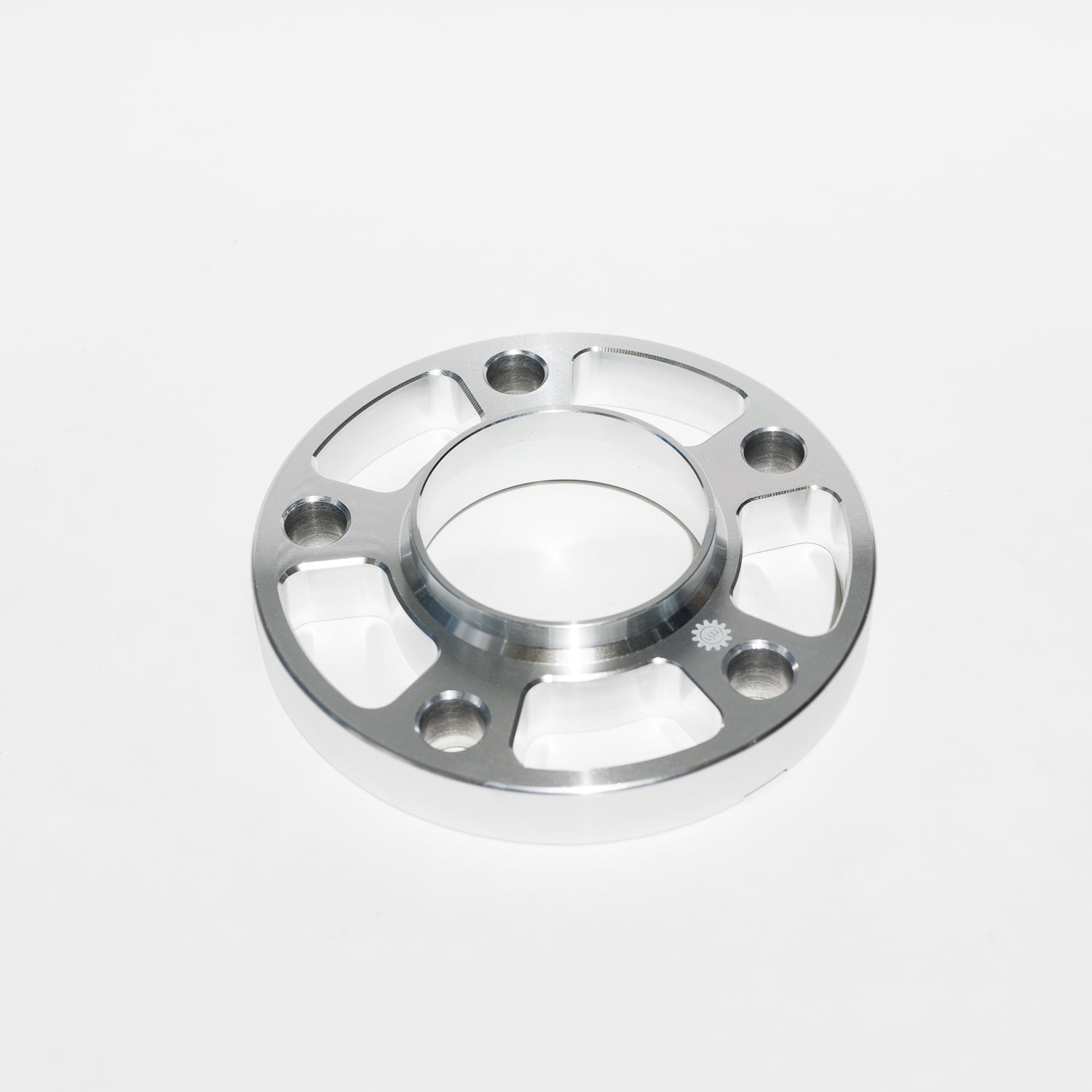
Ultimate BMW Wheel Spacer, Bolts, Studs Size Guide
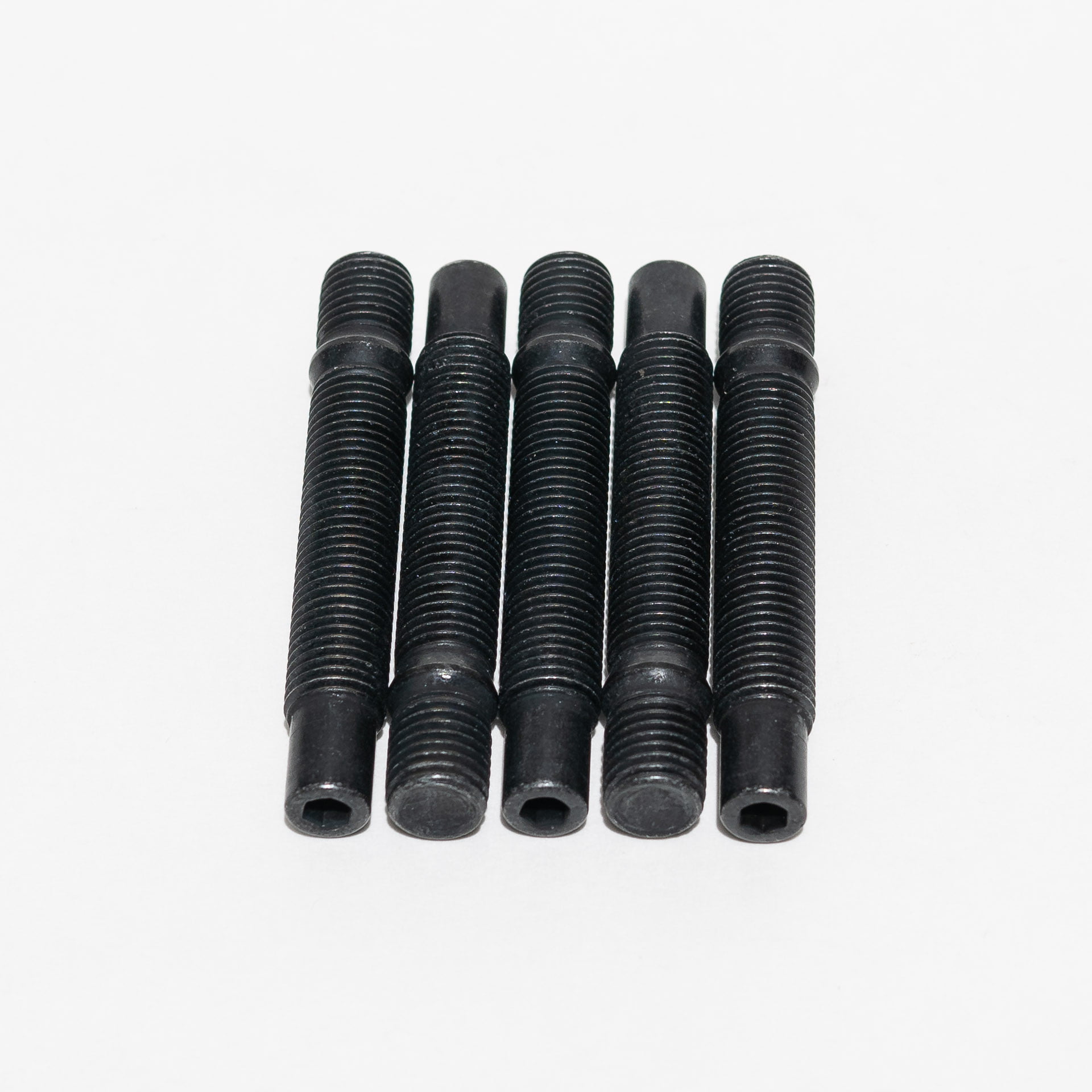
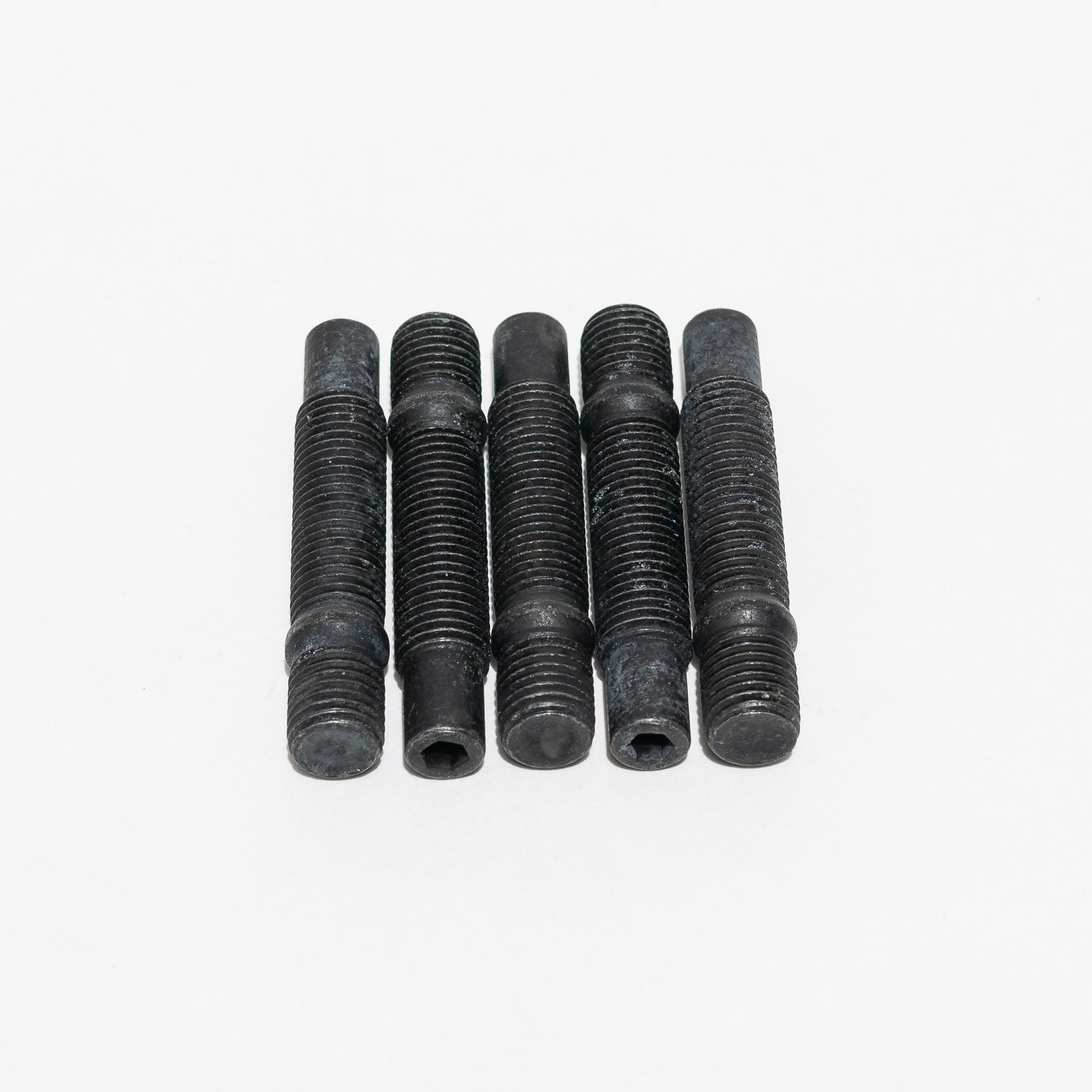
For those of you that are researching wheels, spacers, bolts and stud kits you want to take a look at our BMW Wheel Thread and Bolt Pattern Guide. Getting the right hardware is critical as there is a minimum engagement length and number of turns required for each car. For 12×1.50mm bolts you need approximately 10mm of length or 6.5 turns. With 14×1.25 you need 12mm in length or 9.0 turns. 14×1.50 will require 12mm in length or 7.5 turns. If you don’t meed the minimum engagement, your studs or bolts will most likely fail prematurely.
BMW Wheel Thread and Bolt Pattern Guide
| SERIES | YEAR | BOLT PATTERN | LUG SIZE (mm) | LUG TYPE | CENTER BORE (mm) |
|---|---|---|---|---|---|
| 1 Series | 2008+ | 5x120 | M12x1.5 | Conical Bolt | 72.56 |
| 2 Series | 2014+ | 5x120 | M14x1.25 | Conical Bolt | 72.56 |
| 3 Series | 1979-1991 | 4x120 | M12x1.5 | Conical Bolt | 57.10 |
| 3 Series | 1992-2013 | 5x120 | M12x1.5 | Conical Bolt | 72.56 |
| 3 Series | 2014+ | 5x120 | M14x1.25 | Conical Bolt | 72.56 |
| 4 Series | 2014+ | 5x120 | M14x1.25 | Conical Bolt | 72.56 |
| 5 Series | 1975-1996 | 5x120 | M12x1.5 | Conical Bolt | 72.56 |
| 5 Series | 1997-2010 | 5x120 | M12x1.5 | Conical Bolt | 74.10 |
| 5 Series | 2011+ | 5x120 | M14x1.25 | Conical Bolt | 72.56 |
| 6 Series | 1975-1988 | 5x120 | M12x1.5 | Conical Bolt | 72.56 |
| 6 Series | 2010+ | 5x120 | M12x1.5 | Conical Bolt | 72.56 |
| 6 Series | 2011+ | 5x120 | M14x1.25 | Conical Bolt | 72.56 |
| 7 Series | 1975-1987 | 5x120 | M12x1.5 | Conical Bolt | 72.56 |
| 7 Series | 2010+ | 5x120 | M14x1.25 | Conical Bolt | 72.56 |
| 8 Series | 1992+ | 5x120 | M12x1.5 | Conical Bolt | 72.56 |
| M3 | 1988-2013 | 5x120 | M12x1.5 | Conical Bolt | 72.56 |
| M3 | 2014+ | 5x120 | M14x1.25 | Conical Bolt | 72.56 |
| M5 | 1985-1995 | 5x120 | M12x1.5 | Conical Bolt | 72.56 |
| M5 | 1998-2003 | 5x120 | M12x1.5 | Conical Bolt | 74.10 |
| M5 | 2005-2010 | 5x120 | M12x1.5 | Conical Bolt | 72.56 |
| M5 | 2011+ | 5x120 | M14x1.25 | Conical Bolt | 72.56 |
| M6 | 1983-2010 | 5x120 | M12x1.5 | Conical Bolt | 72.56 |
| M6 | 2011+ | 5x120 | M14x1.25 | Conical Bolt | 72.56 |
| Z8 | 2001+ | 5x120 | M12x1.5 | Conical Bolt | 72.56 |
| X3 | 2004-2010 | 5x120 | M14x1.5 | Conical Bolt | 72.56 |
| X3 | 2011+ | 5x120 | M14x1.25 | Conical Bolt | 72.56 |
| X5 | 2001-2005 | 5x120 | M14x1.5 | Conical Bolt | 74.10 |
| X5 | 2006-2013 | 5x120 | M14x1.25 | Conical Bolt | 74.10 |
| X5 | 2014+ | 5x120 | M14x1.25 | Conical Bolt | 74.10 |
| X6 | 2008+ | 5x120 | M15x1.5 | Conical Bolt | 74.10 F / 72.56 R |
| Z3 M | 1996+ | 5x120 | M12x1.5 | Conical Bolt | 72.56 |
| Z4 M | 2006+ | 5x120 | M12x1.5 | Conical Bolt | 72.56 |
Spacers, Studs & Bolts Guide
| Thread Pitch | OEM Engagement Length (mm) | Spacer Size (mm) | Required Bolts (mm) | Required Studs (mm) |
|---|---|---|---|---|
| M12x1.5mm | 10 | 0 | 25 | 75 |
| M12x1.5mm | 10 | 3 | 28 | 75 |
| M12x1.5mm | 10 | 5 | 30 | 75 |
| M12x1.5mm | 10 | 12 | 38 | 75 |
| M12x1.5mm | 10 | 15 | 40 | 90 |
| M12x1.5mm | 10 | 20 | 45 | 90 |
| M12x1.5mm | 10 | 25 | 50 | 90 |
| M14x1.25 | 12 | 0 | 28 | 75 |
| M14x1.25 | 12 | 3 | 31 | 75 |
| M14x1.25 | 12 | 5 | 33 | 75 |
| M14x1.25 | 12 | 12 | 40 | 75 |
| M14x1.25 | 12 | 15 | 43 | 90 |
| M14x1.25 | 12 | 20 | 48 | 90 |
| M14x1.25 | 12 | 25 | 53 | 90 |
| M14x1.5 | 12 | 0 | 28 | 75 |
| M14x1.5 | 12 | 3 | 31 | 75 |
| M14x1.5 | 12 | 5 | 33 | 75 |
| M14x1.5 | 12 | 12 | 40 | 75 |
| M14x1.5 | 12 | 15 | 43 | 90 |
| M14x1.5 | 12 | 20 | 48 | 90 |
| M14x1.5 | 12 | 25 | 53 | 90 |
-

78mm M12x1.5mm Race Studs - Pure Bullet
Price range: $5.00 through $105.00-
82mm M12x1.5mm Race Studs - Hex Head
Price range: $6.00 through $130.00-
68mm M12x1.5mm Race Studs - Hex Head
Price range: $5.00 through $118.00-

90mm M12x1.5mm Race Studs - Hex Head
Price range: $6.00 through $137.00-

75mm M12x1.5mm Race Studs - Hex Head
Price range: $6.00 through $124.00-

-

-

-

-
-

-


#GRIDLIFE Time Attack at Streets of Willow
Check out the Time Attack at Streets of Willow! #GRIDLIFE Streets Special video that was made by Gears and Gasoline. If you’re not familiar with GRIDLIFE they throw some of the best event/festivals for the auto enthusiast community but they’re mostly done in the east coast – actually all of them. Until this.
They came out to Street of Willow to do a bracket style head to head time attack battle. Pretty much the same format as Formula DRIFT where you need to close the gap, but actually timed in seconds.
The video doesn’t tell the story that well, but I had a blast doing runs with Vinny in his E46 M3. (My twin) We basically were neck and neck most of the time. He ended up taking the W, but damn that adrenaline rush is something new.
You can also see Connie and Allison in the video doing some rollers at the end. Check it out!

Almost Crashing Into Vinny's E46 M3
GRIDLIFE Battle at Streets of Willow CCW going against Vinny Anatra and his E46 M3. This was our One More Time battle and my strategy was to let him go first so I can give him pressure. Coming down the front straight going into the skid pad, I late braked, but the car wouldn’t stop because of knock back on the Stoptech ST-40 so I had to veer off my line. I tried my best to stay with him, but he ended up taking the W. Super fun battle though!
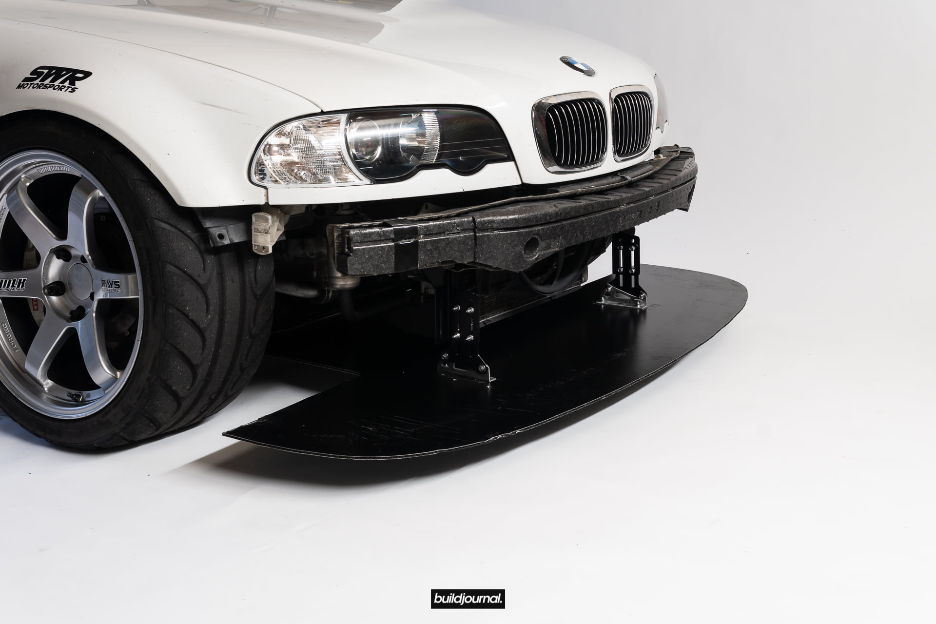
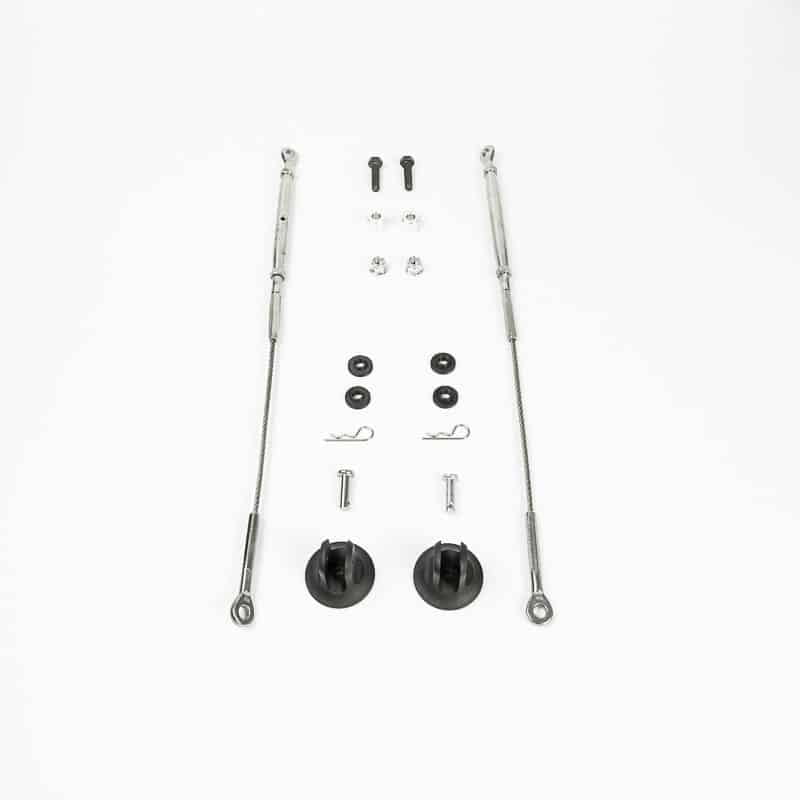
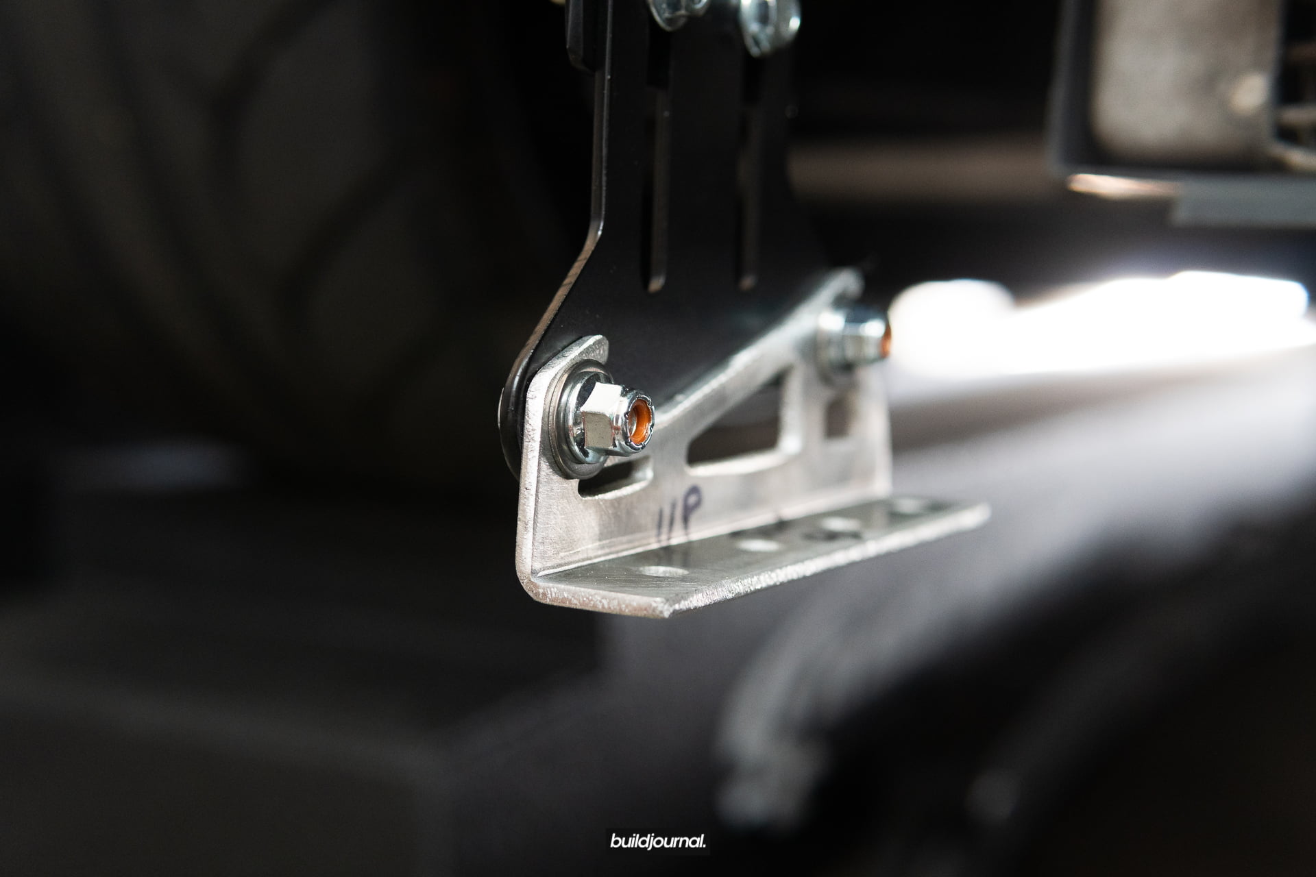
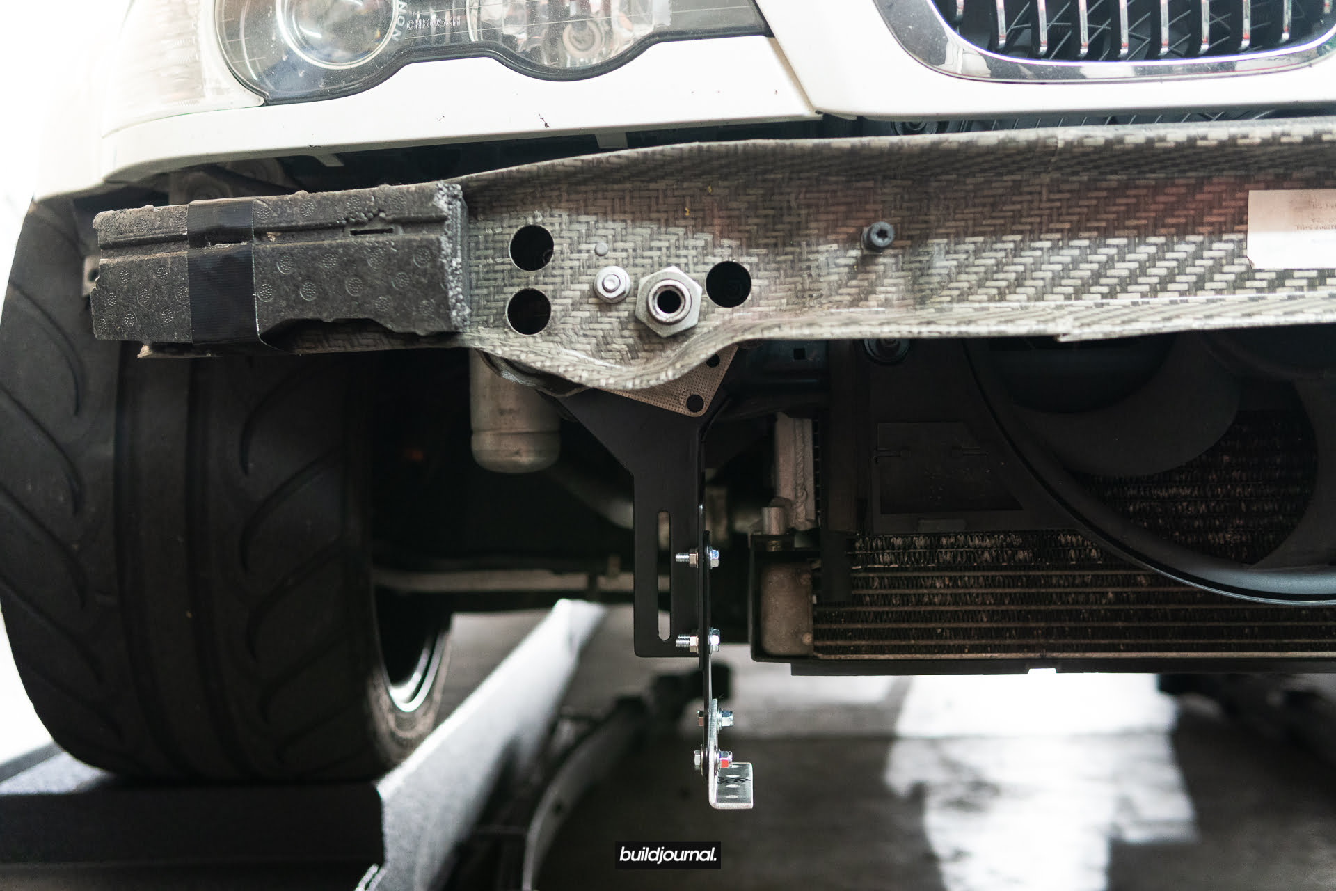
Quick-Release Adjustable Front Splitter Brackets Install DIY
Here are the install DIY for our Quick-Release Adjustable Front Splitter Brackets and Front Race Splitter. You’re going to need to jack up the car and remove your bumper to do this install. The removal of the bumper support beam is also required. Models dating up to 2003 have the aluminum carrier and 2003.5 and up have the kevlar so make sure you check to see which one you have. This install will take about 1-2 hours. Everything is bolt-on and you just need basic tools. To get an idea of the bracket and splitter installation, first watch the quick-release demonstration video below.
Tools required
- 13mm socket
- 10mm socket and wrench
- 8mm wrench
- 1/4″ drill bit and drill
- 5/32 allen key
- Marker
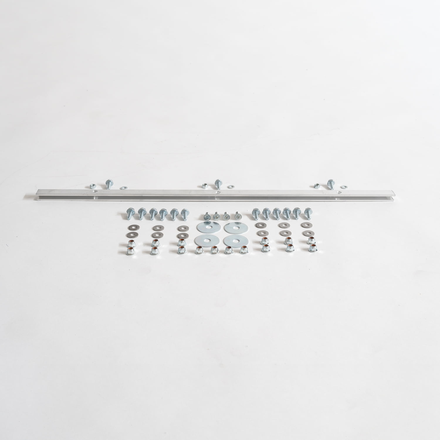
Quick-Release Adjustable Front Splitter Brackets Parts list
| Part No. | Part Name | Quantity |
|---|---|---|
| 1 | Steel Bumper Bracket | 2 |
| 2 | Steel Adjustment Bracket | 2 |
| 3 | Steel Feet w/ Pin | 2 |
| 4 | M6 20mm Serrated-Flange Hex Head Screws | 8 |
| 5 | M6 Nylon-Insert Flange Locknut | 12 |
| 6 | M6 18mm Hex Drive Flat Head Screw | 4 |
| 7 | M7 Hex Nut | 8 |
| 8 | 3/8″ 1.5″ OD Washer | 4 |
Race Splitter Parts List
| Part No. | Part Name | Quantity |
|---|---|---|
| 1 | Race Splitter | 1 |
| 2 | U-Channel (optional) | 1 |
| 3 | M6 12mm Hex Head Screw (included with U-Channel) | 3 |
| 4 | M6 12mm OD Washer (included with U-Channel) | 3 |
| 5 | M6 Nylon-Insert Locknut (included with U-Channel) | 3 |
| 6 | Splitter Guard (optional) | 1 |
Splitter bracket install directions
1. Remove front bumper.
2. Remove aluminum or kevlar carrier from bumper with 13mm socket.
3. Remove front undertray.
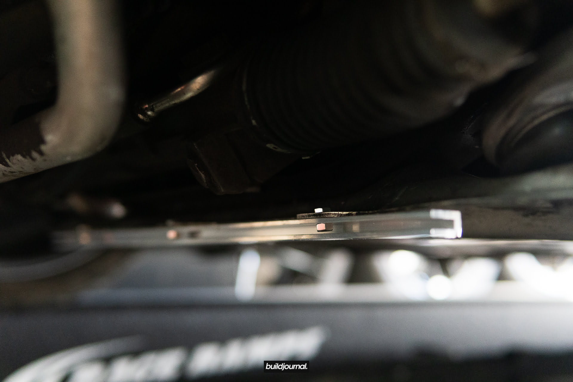
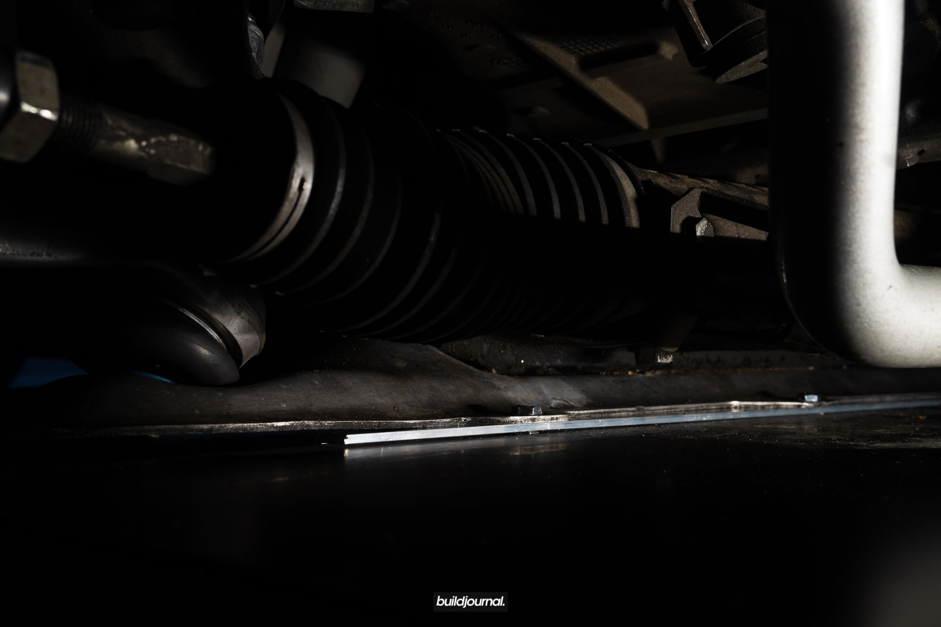
4. Install U-Channel with the supplied (3) M6 12mm Hex Head Screws, (3) M6 12mm OD Washers, and (3) M6 Nylon-Insert Locknuts. You will install using the existing 3 OEM front brace holes that connected to the under tray. Line up the 10mm nuts in the channel first and slowly position it into place. Insert the 10mm bolts through the top of the 3 OEM front brace holes.

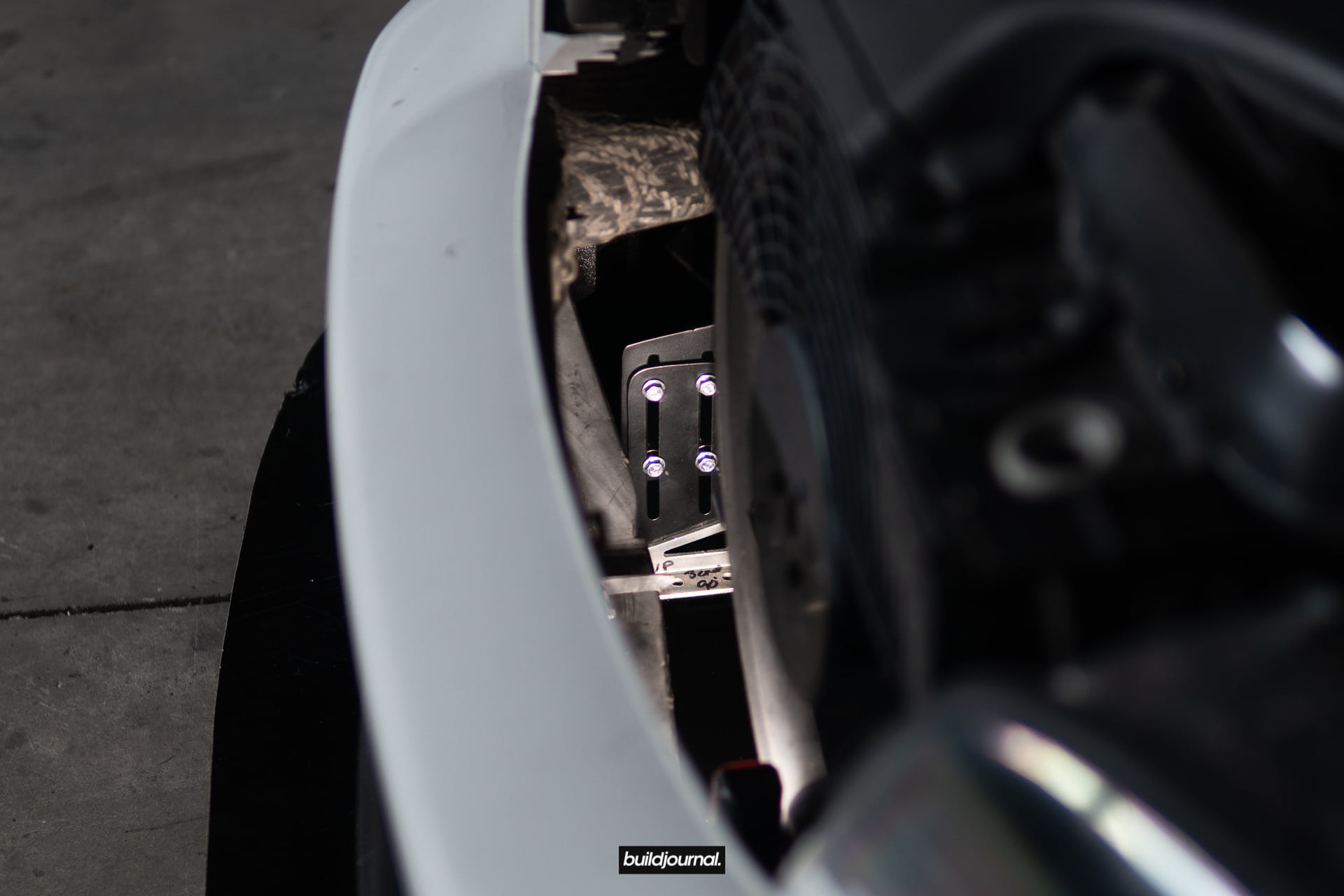
5. Install Steel Bumper Brackets on each side.
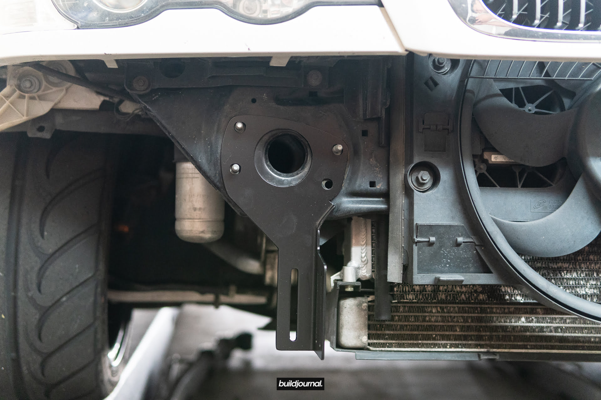


6. Install Steel Adjustment Brackets on each side using (8) M6 16mm Serrated-Flange Hex Head Screws, (8) M6 Nylon-Insert Flange Locknuts, and (8) M6 18mm OD Washers. You can preset the height for now in reference to how it’s shown in the picture. You’re going to need to micro-adjust the height in the last step, but this should be a good preset for running the ACS lip and stock OEM bumper.

7. Install Aluminum Feet with (4) M6 20mm Serrated-Flange Hex Head Screws and (4) M6 Nylon-Insert Flange Locknuts. Apply hand tight.
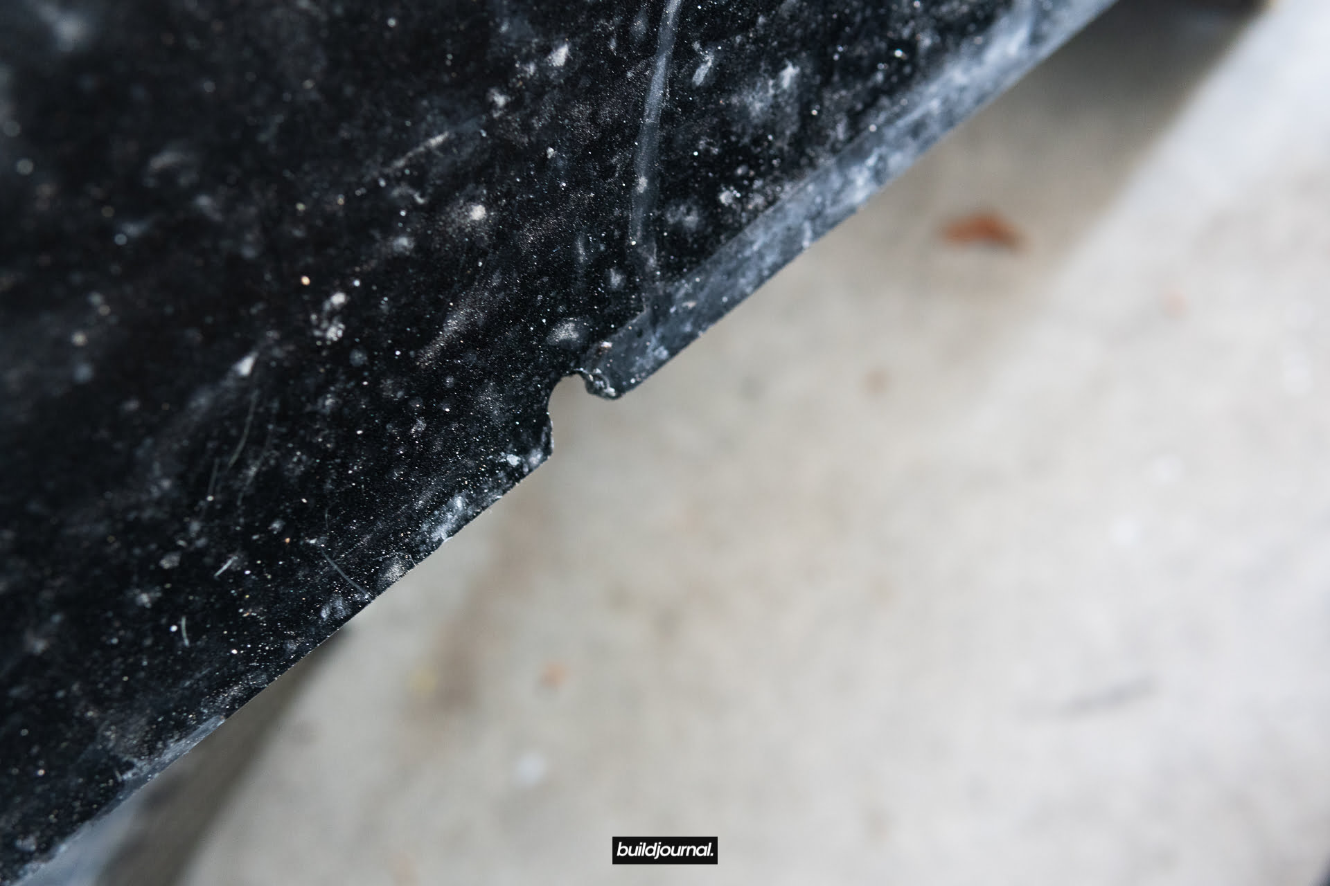
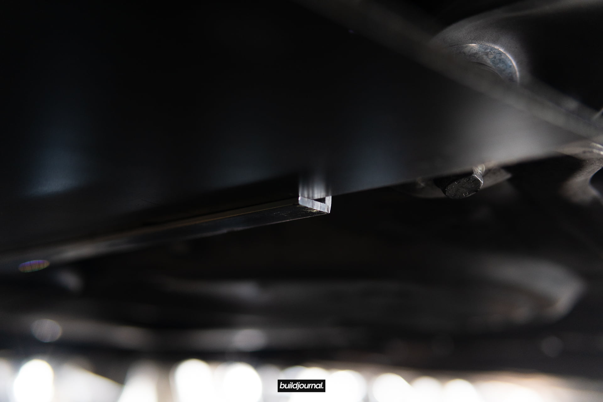
8. Observe the 3 cutouts on the Buildjournal Race Splitter. These are cut inwards to sit flush against the U-Channel.
9. Reinstall the bumper carrier and install 13mm OEM nuts.
10. Slide the splitter into the U-Channel. Double check to make sure the splitter sits flush and back against the U-Channel.
11. Align the splitter in the middle and hold pressure against the back of the U-Channel. Carefully raise the splitter up against the aluminum feet and mark the drill locations using a marker.
12. Use the (4) M6 18mm Hex Drive Flat Head Screws, (4) M6 18mm OD Washers, and (4) M6 Nylon-Insert Flange Locknuts to install splitter onto Aluminum Feet.
13. Check the top and bottom of the splitter to see if seating is still in proper position all the way against the back of the U-Channel. Tighten down the feet to the splitter.

14. Adjust the Steel Adjustment Brackets to set your desired height and tighten everything down. Install your bumper back on.
PRO TIP: Since I have my radiator shrouds removed, I can disconnect the splitters from the engine bay, top down. This makes it a super easy and fast removal whenever I need to get on the trailer or doing an oil change.

GRIDLIFE 2019 Streets of Willow CCW - 1:25.653
GRIDLIFE hosted their first ever event in the west coast for a head to head bracket elimination style track battle and I entered to see what it's about. The event is widely popular in the east coast due to the "festival" type of event that it organizes. It's basically a track day, but with car shows, music and food. If you ever been to Bimmerfest at Auto Club Speedway it's kind of like that vibe.
The morning consisted of 3 regular track sessions, however those that were in the competition had to set a qualifying lap time during those 3 sessions. The fastest of the bunch got to compete in the bracket finals. I went up against another E46 M3 and I ended up advancing. Next I faced Vinny Anatra, from Hoonigan, in his E46 M3 and it was such a rad experience. There's a competition element to the format so the energy is more intense than normal track days. It's almost like the first track day I've ever done where I'm nervous and just dosing off through the window as I sit on the hot pit waiting to go out. It was a refreshing experience. Something different than just a HPDE "time attack" track day.
We each got 2 runs and whoever takes 2 wins. Vinny led the first run and I ended up beating him. On the 2nd run, Vinny was in the chase and he ended up beating me. So it was 1 and 1 so we had to go One More Time. At the end Vinny ended up beating me, but the whole experience was such a thrill. I would do it again if they came back for another event. There's nothing like the feeling of going heads up with the entire track to ourselves and battling it out in a bumper to bumper fashion.